Interchangeable sandal and related methods

a technology of interchangeable sandals and sandals, applied in the field of interchangeable sandals, can solve the problems of not being aesthetically pleasing, not being functionally sound, and being highly fashionable and expensive, and achieve the effect of increasing the overall thickness of the sole itsel

a technology of interchangeable sandals and sandals, applied in the field of interchangeable sandals, can solve the problems of not being aesthetically pleasing, not being functionally sound, and being highly fashionable and expensive, and achieve the effect of increasing the overall thickness of the sole itsel

US20080060227A1Inactive Publication Date: 2008-03-13ENDERSON J PATRICK

Image

  • Interchangeable sandal and related methods
  • Interchangeable sandal and related methods
  • Interchangeable sandal and related methods

Examples


Embodiment Construction

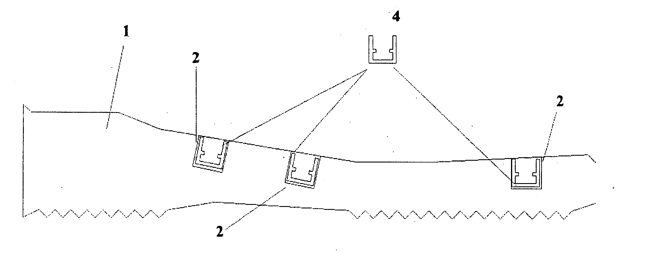
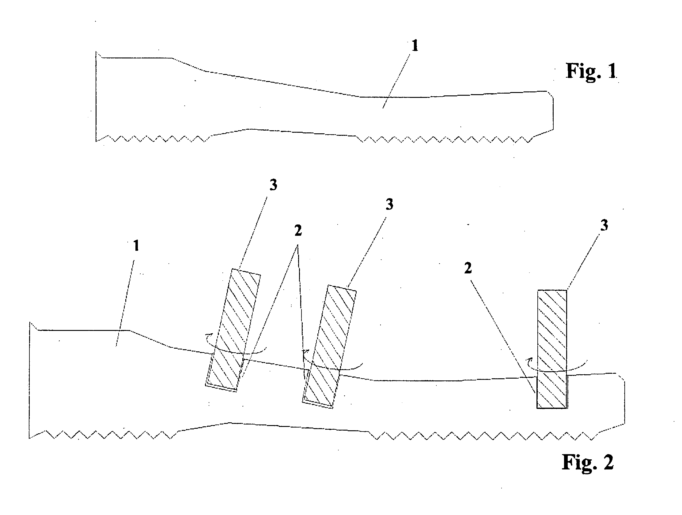
[0028] Referring now more particularly to the drawings in which like reference numerals indicate like parts throughout the several views, FIGS. 1 and 2 are schematic illustrations of a treaded sandal (or flip flop) sole base showing some simplified manufacturing steps in accordance with an example embodiment. The evolutionary interchangeable sandal system, according to an example embodiment of the invention, utilizes a sandal sole base 1 as shown in FIG. 1, which may include one or more positioning ports 2 as shown in FIG. 2. Ports 2 may be obtained in the manufacturing process indirectly through machining (e.g., via tools 3) or directly (e.g., via mold extrusion). Sole base 1 may be formed from any suitable material having sufficient flexibility for the correct movement of the foot.

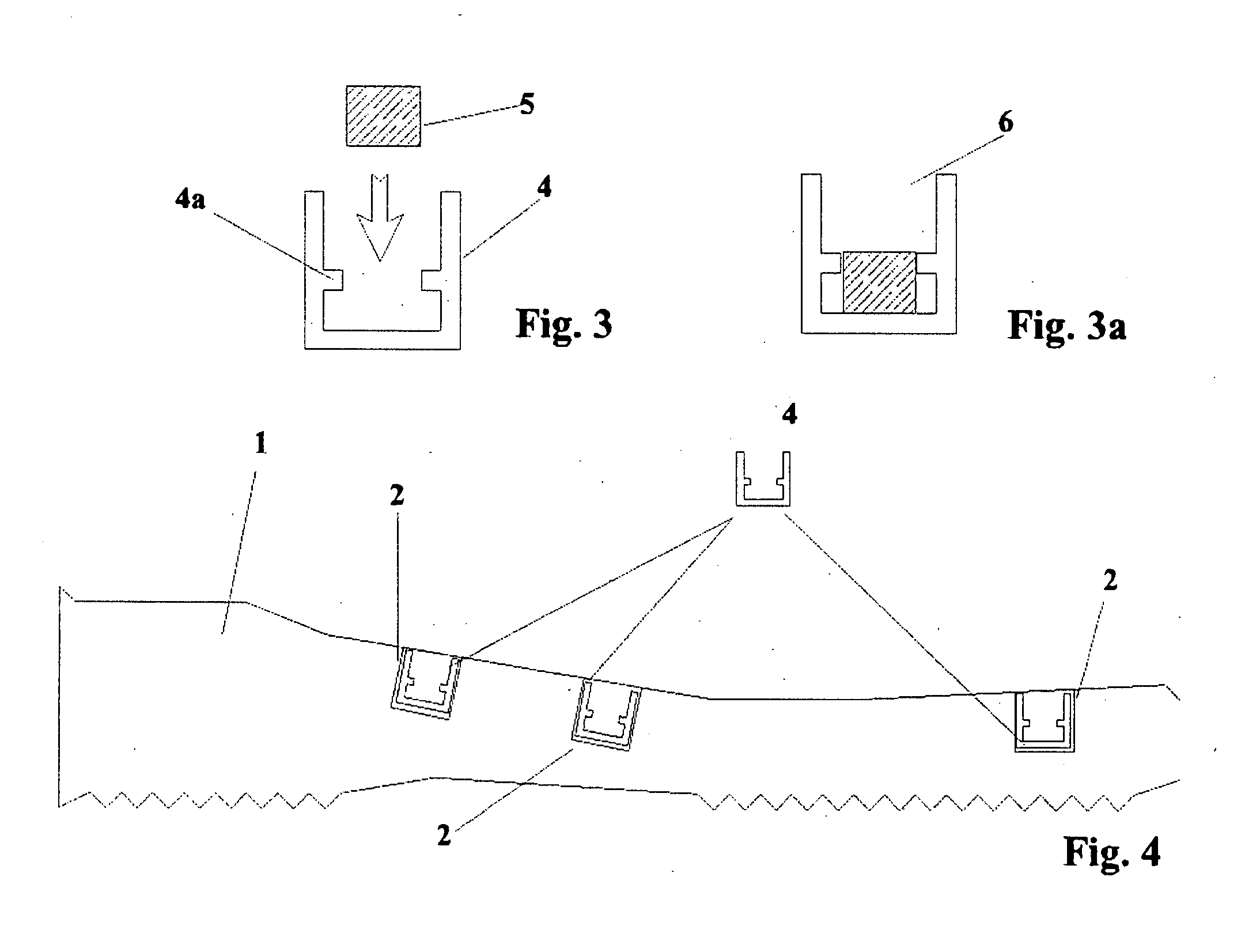
[0029] In FIG. 3, the fastener system is formed by a locking structure 4, locking mechanism (or locking arms) 4a, and a dampening system 5. The materials utilized to form the fastener system may be mate...


PUM


Abstract

Various embodiments of an evolutionary interchangeable sandal are disclosed. Certain example embodiments described herein relate to various sandal configurations that utilize at least two main elements, including a platform sole base and a strap assembly. These elements may be joined by special fasteners that provide quick-connect or disconnect while securely maintaining sandal integrity and wearability. The platform sole base may be customized in various thicknesses and sandal sizes. The strap assembly may be customized in various shapes, colors, styles, and / or manufacturing materials. In the case of the sole tread / height enhancement addition, the soles tread and height may be interchanged as needed.

Description

CROSS-REFERENCE TO RELATED APPLICATION [0001] This application claims the benefit of U.S. provisional patent application No. 60 / 842,673, filed on Sep. 7, 2006, the entire content of which is hereby incorporated herein by reference.FIELD OF THE INVENTION [0002] Certain example embodiments described herein relate to several distinct unassembled elements which, when assembled, comprise a functional, updatably fashionable, and interchangeable sandal. More particularly, certain example embodiments described herein relate to various sandal configurations that utilize at least two main elements, including a platform sole base and a strap assembly. These elements may be joined by special fasteners assuring quick-connect or disconnect while securely maintaining sandal integrity and sandal sizes. The strap assembly may also be customized to various thicknesses and / or sandal sizes. The strap assembly may also be customized in various shapes, colors, styles, and / or manufacturing materials while...

Claims


Application Information

Patent Timeline
13 Mar 2008
Publication
US20080060227A1
IPC
A43B3/24; A43B13/28; A43B23/20; A43B3/12
CPC
A43B3/122; A43B3/103
Inventors
ENDERSON, J. PATRICK