Control device for synchronous motor

a synchronous motor and control technology, applied in the direction of motor/generator/converter stopper, electronic commutator control, dynamo-electric converter control, etc., can solve the problems of large rotational pulsation, difficult to resolve variations of motor individuals, and large rotational pulsation, so as to reduce the scale of the integrated circuit, suppress the rotational pulsation, and solve the individual variation

Active Publication Date: 2008-03-13
RENESAS ELECTRONICS CORP
View PDF6 Cites 14 Cited by
  • Summary
  • Abstract
  • Description
  • Claims
  • Application Information

AI Technical Summary

Benefits of technology

[0010] Moreover, it is possible to resolve Individual variation as long as it is a method of observing the disturbance itself with the observer and suppressing the disturbance as in Patent Document 3. However, also in such method, its control algorithm is complex and the scale of the integrated circuit is greatly increased.
[0011] In view of such problems, an object of the present invention is to provide a control technology of a synchronous motor capable of suppressing rotational pulsations caused by individual variation without getting complexity to the control algorithm.

Problems solved by technology

In these cases, distortion components are generated even if a sinusoidal voltage is applied, thereby causing rotational pulsations.
If variations exist in the three-phase windings, secondary harmonic pulsation components are generated, thereby posing a large rotational pulsation.
In these methods, it is difficult to resolve variations of motor individuals when realizing a driver with a dedicated integrated circuit.
A learning function may be provided to the driver itself, but in this case, the scale of the integrated circuit may be greatly increased, and at the same time, complex control process must be installed.

Method used


Image

  • Control device for synchronous motor
  • Control device for synchronous motor
  • Control device for synchronous motor

Examples


first embodiment

[0036] A motor drive system according to a first embodiment of the control device for a synchronous motor of the present invention will be described with reference to FIG. 1 to FIG. 6.

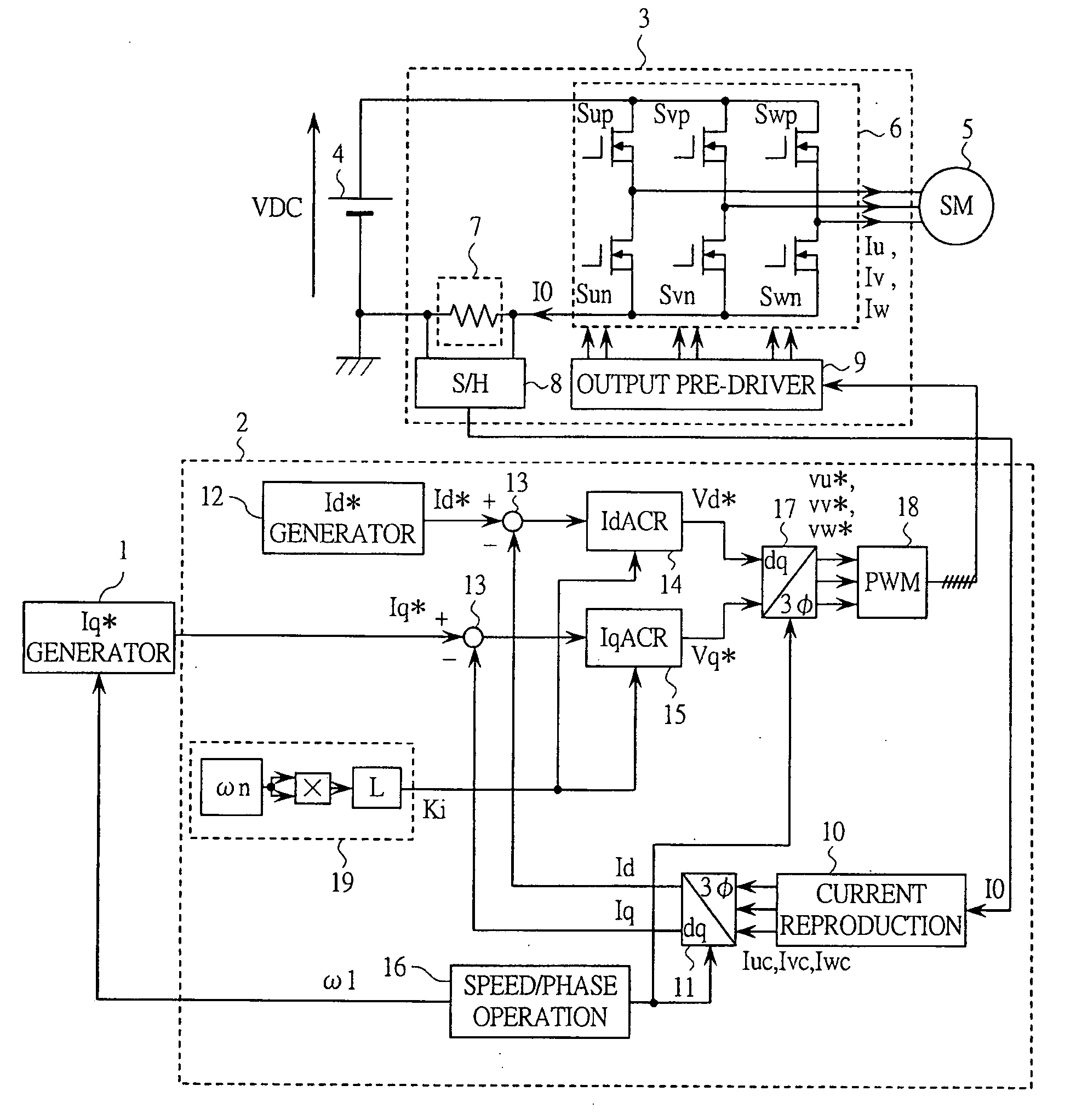
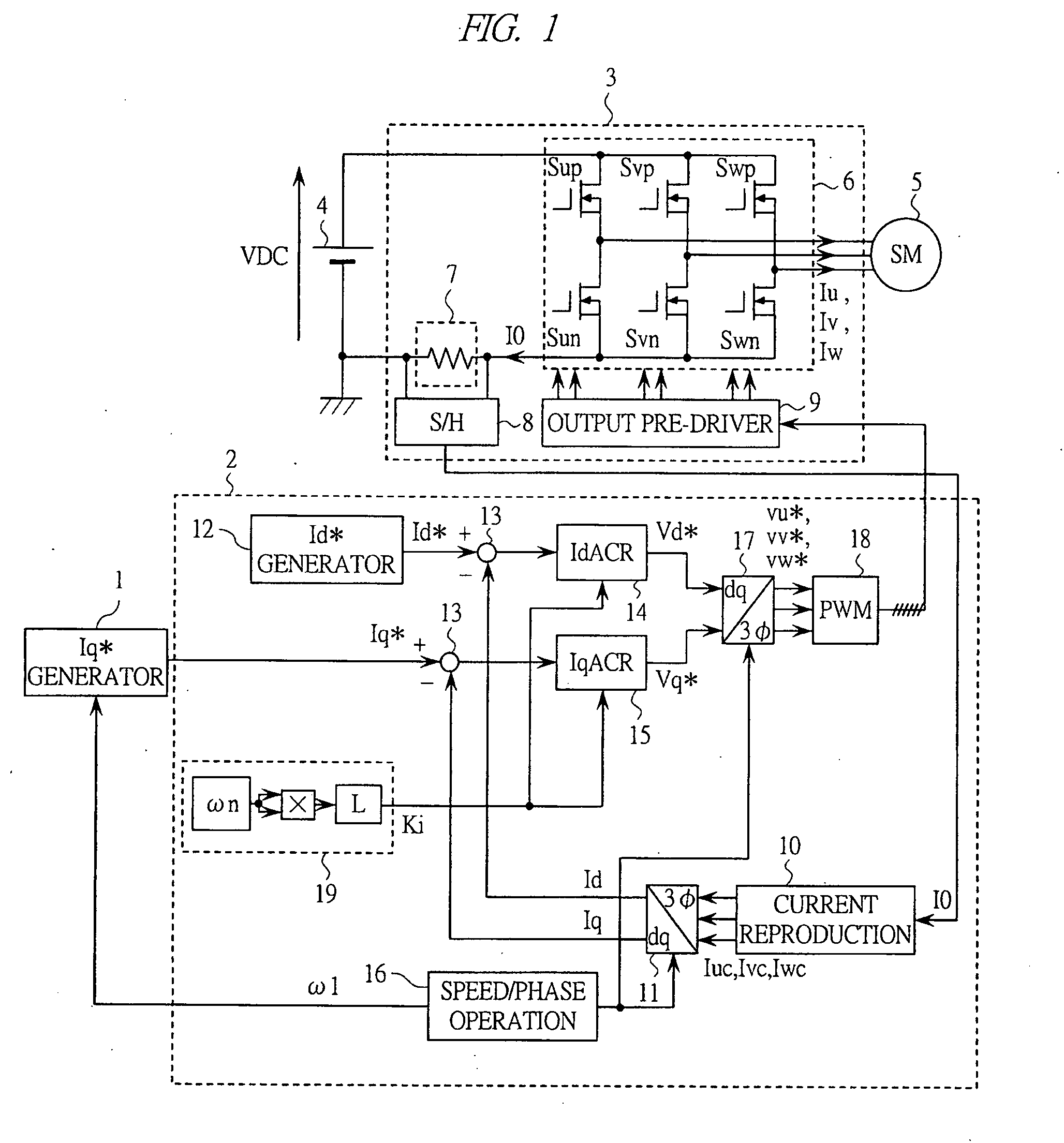
[0037]FIG. 1 shows a configuration of the motor drive system according to the present embodiment. The motor drive system shown in FIG. 1 is configured by: an Iq* generator 1 for generating a current command corresponding to the torque of the motor: a controller 2 for calculating an applied voltage to the motor and generating a pulse-width modulated wave (PWM) signal for an inverter; the inverter 3 for generating an alternating current voltage from a direct current voltage in response to the PWM signal from the controller 2; a DC power supply 4 which is the power supply of the inverter 3; and a synchronous motor 5 controlled by these components. A load device (not shown) is connected to the synchronous motor 5.

[0038] The inverter 3 is configured by: an inverter main circuit unit 6 configured by six sw...

second embodiment

[0063] A motor drive system according to a second embodiment of the control device for a synchronous motor of the present invention will be described with reference to FIG. 7.

[0064]FIG. 7 shows a configuration of a controller in the motor drive system of the present embodiment.

[0065] In the present embodiment, a control device for a synchronous motor 2B is used in place of the controller 2 of FIG. 1 to realize the motor drive system.

[0066] In FIG. 7, reference numerals 10 to 18 indicate the components same as those in FIG. 1. The major difference with FIG. 1 is in the difference in the operation of the integral gain setting unit 19B.

[0067] In the first embodiment of FIG. 1, the integral gain Ki is determined with respect to the set value of ωn. Thus, the set value must be changed when the pulsation frequency is changed. The actual pulsation component of the motor becomes the component of twice or six times as high as the driving frequency of the motor, and thus the value of on c...

third embodiment

[0071] A motor drive system according to a third embodiment of the control device for a synchronous motor of the present invention will be described with reference to FIG. 8 and FIG. 9.

[0072]FIG. 8 shows a configuration of a controller in the motor drive system of the present embodiment.

[0073] In the present embodiment, the control device for a synchronous motor 2C is used in place of the controller 2 of FIG. 1 to realize the motor drive system.

[0074] In FIG. 8, reference numerals 10 to 13, 16 to 18, and 19C indicate the components same as those in FIGS. 1 and 7. The major difference with FIG. 1 and FIG. 7 lies in that a proportional gain setting unit 26 is newly added, and the configuration of the d-axis current controller 14C and the q-axis current controller 15C is modified.

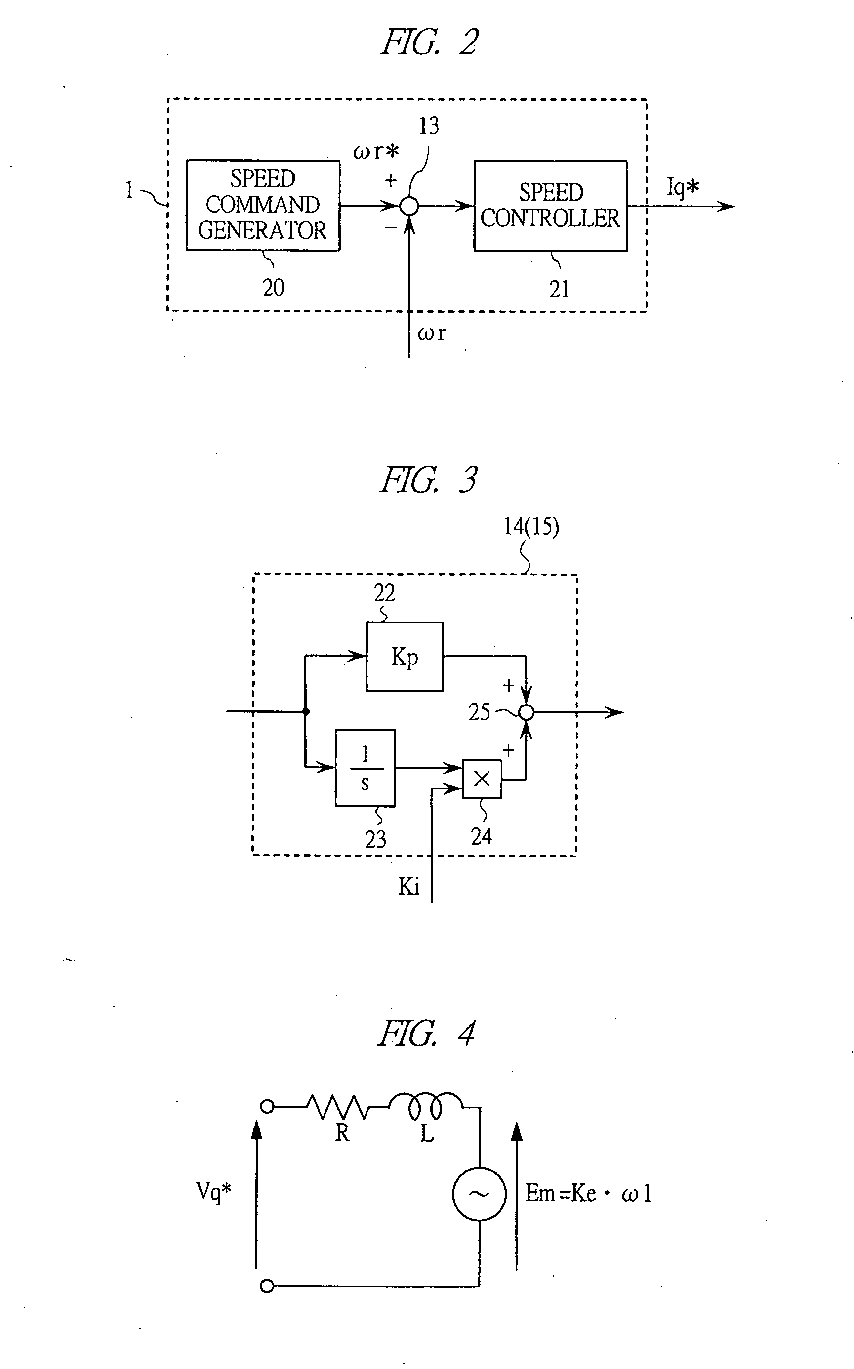
[0075] The d-axis current controller 14C (as well as the q-axis current controller 15C) has the configuration shown in FIG. 9. In FIG. 9, reference numerals 23 to 25 are the same as those in FIG. 3.

[0076]...


PUM


Abstract

A control technology for a synchronous motor for suppressing rotational pulsation caused by variation in individuals without making a control algorithm complex is provided. In a motor drive system which is a control device for a synchronous motor, in order to suppress the pulsation component of N times as high as the AC frequency for driving the synchronous motor, a controller in which the phase property of the disturbance response of the controller with respect to the pulsation frequency is within ±45° is arranged. Therefore, the torque pulsation component generated from distortion in induction voltage or variation between phases is suppressed.

Description

CROSS-REFERENCE TO RELATED APPLICATION [0001] The present application claims priority from Japanese Patent Application No. JP 2006-226315 filed on Aug. 23, 2006, the content of which is hereby incorporated by reference into this application. TECHNICAL FIELD OF THE INVENTION [0002] The present invention relates to a control technology for a synchronous motor. More particularly, the present invention relates to a technology effective when used in a rotation control technology for a spindle motor of hard disc driver (HDD), optical disc driver and the like in a motor driving device and a motor driver integrated circuit device. BACKGROUND OF THE INVENTION [0003] For example, in the drive system of spindle motors of HDD devices, reduction in rotational pulsation is strongly desired. If the rotational pulsation is large, read or write error occurs, which becomes a great impediment in enhancing the recording density. Furthermore, the rotational pulsation is preferably as small as possible t...

Claims


Application Information

Patent Timeline
Patent Type & Authority Applications(United States)
IPC IPC(8): H02P6/08H02P6/06H02P6/15H02P6/182H02P6/28
CPCH02P21/05H02P6/10
Inventor IWAJI, YOSHITAKAKOKAMI, YASUHIKOKUROSAWA, MINORUNAKATSUGAWA, JUNNOSUKE
Owner RENESAS ELECTRONICS CORP
Why Eureka
Try Eureka