
Receiver circuit having compensated offset voltage

a receiver circuit and offset voltage technology, applied in the field of receiver circuits, can solve the problems of the entire sense amplifier malfunctioning and the transistor malfunctioning, and achieve the effect of preventing the malfunction of the sense amplifier

Inactive Publication Date: 2008-03-13
SK HYNIX INC
View PDF6 Cites 7 Cited by
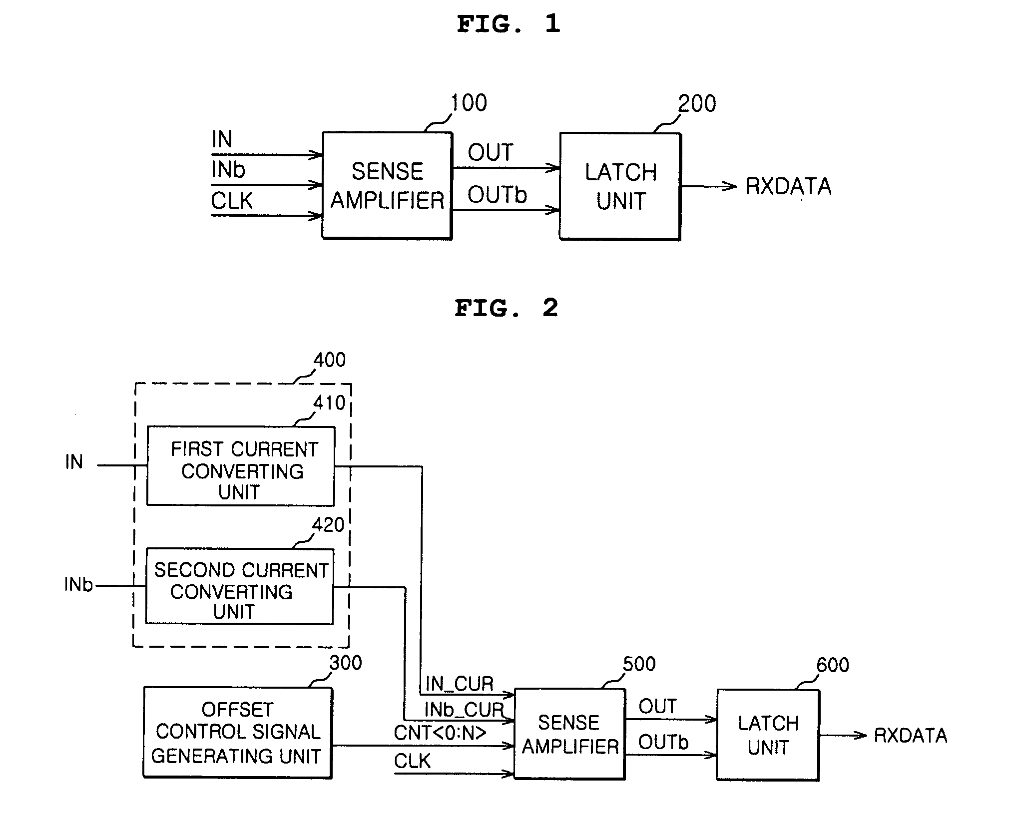
  • Summary
  • Abstract
  • Description
  • Claims
  • Application Information

AI Technical Summary

Benefits of technology

[0013]An embodiment of the present invention provides a receiver circuit that is capable of preventing the malfunction of a sense amplifier.
[0014]Another embodiment of the present invention provides a receiver circuit that is capable of preventing the malfunction caused by an offset voltage or noise.

Problems solved by technology

In this case, unexpected noise may be input to any one of the transistors of the input unit, which causes malfunction of the transistor.
The offset voltage and noise may cause malfunction of the input unit of the sense amplifier such that an electric potential at the connection node of the input unit and the amplifying unit is changed, which results in the malfunction of the entire sense amplifier.

Method used


Image

  • Receiver circuit having compensated offset voltage
  • Receiver circuit having compensated offset voltage
  • Receiver circuit having compensated offset voltage

Examples


Embodiment Construction

[0022]The present invention will now be described more fully with reference to the accompanying drawings, in which exemplary embodiments of the invention are shown. The invention may, however, be embodied in many different forms and should not be construed as being limited to the embodiments set forth herein; rather, these embodiments are provided so that this disclosure will be thorough and complete, and will fully convey the concept of the invention to those skilled in the art.

[0023]Referring to FIG. 2, a receiver circuit according to an embodiment includes an offset control signal generating unit 300, a current converting unit 400, a sense amplifier 500, and a latch unit 600.

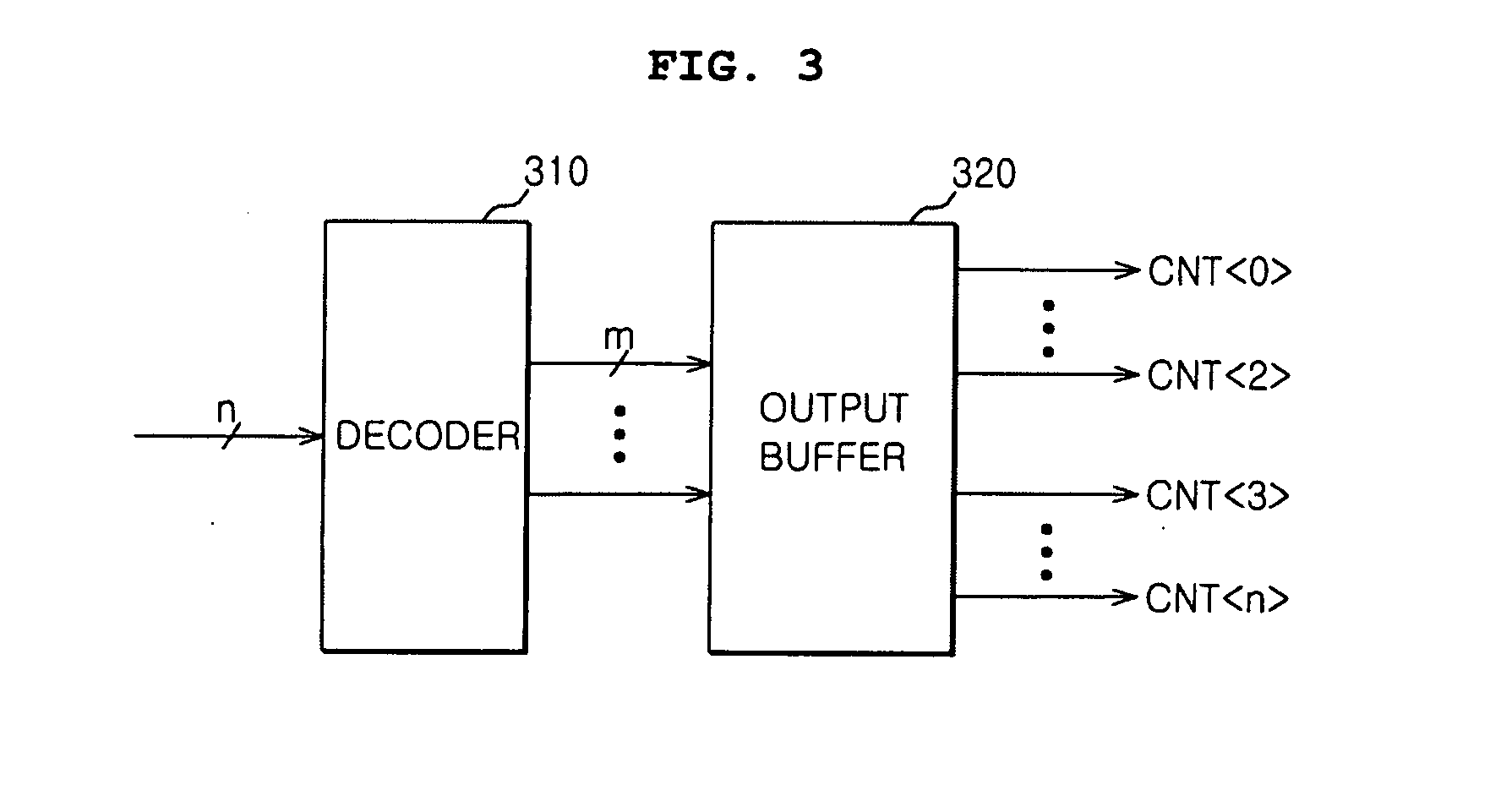
[0024]The offset control signal generating unit 300 outputs a plurality of offset control signals CNT0:N>. The offset voltage may be a voltage difference caused by the offset of the transistors configuring the sense amplifier 400. The number of offset control signals CNT0:N> to be activated may change dependi...


PUM


Abstract

A receiver circuit includes an offset control signal generating unit that outputs a plurality of offset control signals using an offset voltage. A sense amplifier receives a first current and a second current generated on the basis of an up input signal and a down input signal, respectively, converts the first current and the second current into an up compensating signal and a down compensating signal having electric potentials compensating the offset voltage, and amplifies the up compensating signal and the down compensating signal to output an up output signal and a down output signal.

Description

CROSS-REFERENCE TO RELATED PATENT APPLICATION[0001]This application claims the benefit of Korean Patent Application No. 10-2006-0088745, filed on Sep. 13, 2006, in the Korean Intellectual Property Office, the disclosure of which is incorporated herein in its entirety by reference.BACKGROUND OF THE INVENTION[0002]1. Technical Field[0003]The present invention relates to a receiver circuit, and in particular, to a receiver circuit that amplifies input data.[0004]2. Related Art[0005]Generally, a receiver circuit in a semiconductor integrated circuit is used to amplify data by increasing the voltage swing when input data is transmitted to an output terminal.[0006]Such a receiver circuit includes a sense amplifier 100 and a latch unit 200, as shown in FIG. 1.[0007]The sense amplifier 100 receives an up input signal IN and a down input signal INb and outputs an up output signal OUT and a down output signal OUTb in response to a clock signal CLK. Such a sense amplifier 100 includes an input...

Claims


Application Information

Patent Timeline
IPC IPC(8): H03F3/42
CPCG11C7/02H03F2203/45354G11C7/08G11C7/1051G11C7/1057G11C7/106G11C7/1078G11C7/109H03F3/45179H03F3/45475H03F3/45766H03F3/45991H03F2203/45136H03F2203/45212H03F2203/45352G11C7/065G11C7/06G11C7/10
Inventor HWANG, TAE JINPARK, KUN WOOKIM, YONG JUKIM, JONG WOONSONG, HEE WOONGOH, IC SUKIM, HYUNG SOO
Owner SK HYNIX INC
Learn More