Phase synchronization circuit and electronic apparatus

Inactive Publication Date: 2008-03-13
SONY CORP
View PDF5 Cites 11 Cited by
  • Summary
  • Abstract
  • Description
  • Claims
  • Application Information

AI Technical Summary

Benefits of technology

[0039]According to an embodiment of the present invention, the gain characteristic information with which the input signal-oscillation frequency conversion gain characteristic of the oscillation unit in the real operating situation is specified by using two types of target frequencies is measured. Then, at the time of the usual phase synchronizing operation, based on the gain characteristic information, the drive unit is controlled so that the product of the frequency conversion gain (Kosci) at the time of actual operation and the drive signal for the loop filters (Icp and Vdr) may be constant. By controlling the product of Kosci and Icp or Vdr to be constant, it becomes possible to prevent the generation of variations in the zone and dumping factor resulting from the variations in the frequency conversion gain.
[0040]Further, as an additional effect, by employing an arrangement in which the product of Kosci and Icp or Vdr is controlled to be constant, it becomes possible to perform the management by “ratio” with which the management accuracy is eased, and the variations in the zone ωn or the dumping factor ζ resulting from the manufacture variations and the temperature changes of the frequency conversion gain can be compensated with high precision. As a result, it is possible to reduce the manufacture variation of the compensation. Further, since it becomes possible to perform the management by “ratio” with which management accuracy is eased, the management of accuracy can be eased also with respect to the structure of the drive unit which performs control for compensation.
[0041]Further, a

Problems solved by technology

However, it is very difficult for the arrangements described in non-patent documents 1 and 2 to compensate completely in the case where the input signal-oscillation frequency conversion gain Kosci of the voltage controlled oscillator is nonlinear.
Further, since the arrangement as described in non-patent document 1 requires to devise a structure of a delay stage, design of circuitry of the delay stage becomes complicated.
Furthermore, since the arrangement as described in non-patent document 2 requires a circuit which creates the current independent of the temperature or manufacture variations, and also requires an arrangement where the created current should be the bias

Method used


Image

  • Phase synchronization circuit and electronic apparatus
  • Phase synchronization circuit and electronic apparatus
  • Phase synchronization circuit and electronic apparatus

Examples


Example

Phase Synchronization Unit; First Embodiment

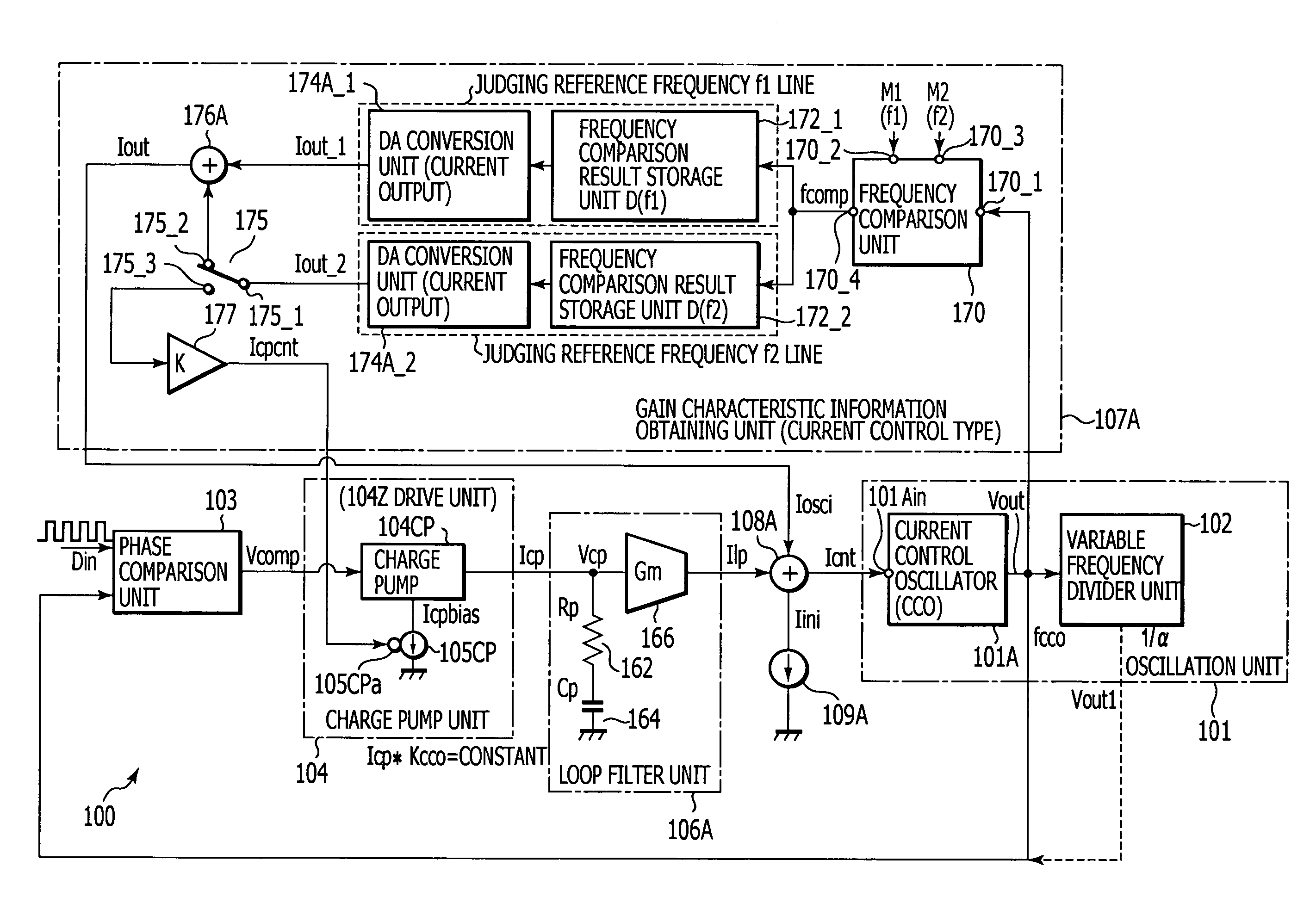
[0117]FIG. 3 is a functional block diagram showing a first embodiment of the phase synchronization unit (phase synchronization circuit) 100. Further, FIG. 4 is a block diagram showing an example of a structure of a phase synchronization unit 100A when not applying the gain characteristic information obtaining unit as a comparative example. It should be noted that this comparative example shows an example in which two charge pumps 104CPs and 104RD are used for the charge pump unit 104, as with the second embodiment to be described later.

[0118]The phase synchronization unit 100 of this embodiment has a first feature that a current control oscillating circuit (CCO; Current Control Oscillator) is employed as the oscillation unit, and has a second feature that current output type one (gain characteristic information obtaining unit 107A) is provided as the gain characteristic information obtaining unit 107 for compensating for the manufacture v...

Example

[0137]In addition, as with the third embodiment, it is possible to raise the function as the low-pass filter by connecting not only the capacitor 164 but also a resistance element 162 of loop filter resistance Rp in series. Unlike the second embodiment, when it is arranged that one charge pump 104CP is provided as a charge pump unit 104, the arrangement where this resistance element 162 is provided is usually adopted.

[0138]Based on the charge pump current Icp outputted from the charge pump 104CP, the voltage / current conversion unit 166 converts the charge pump voltage Vcp generated at one terminal (that is, input of the voltage / current conversion unit 166) of the capacitor 164 into a current signal (referred to as loop filter output current Ilp) according to the voltage current conversion gain Gm.

[0139]When connecting the resistance element 162 and the capacitor 164 in series, the whole voltage current conversion gain (from the charge pump unit 104 to the loop filter unit 106A) is G...

Example

Phase Synchronization unit; Second Embodiment

[0414]FIG. 30 is a functional block diagram showing the second embodiment of the phase synchronization unit (phase synchronization circuit) 100. The phase synchronization unit 100 of the second embodiment has a feature that two charge pumps 104CPs and 104RD are used for the charge pump unit 104 like FIG. 4 shown as a comparative example in the first embodiment. As a whole, this is the same as that of the first embodiment since both the oscillation unit 101 and the control system (the loop filter unit 106A and the gain characteristic information obtaining unit 107A) operate in the current mode. Hereafter, differences from the first embodiment will be mainly described.

[0415]In the phase synchronization unit 100 of the second embodiment, firstly, the gain characteristic information obtaining unit 107A includes a current / current conversion unit 178 for outputting the control current Icpcnt and control current Irdcnt, instead of the current / cu...


PUM


Abstract

A phase synchronization circuit and an electronic apparatus equipped with the phase synchronization circuit are provided. The phase synchronization circuit includes an oscillation unit, a phase comparison unit, a loop unit, a drive unit, an oscillation control signal unit, and a gain characteristic information obtaining unit. In the phase synchronization unit, a compensation signal is generated based on the gain characteristic information obtained by the gain characteristic information obtaining unit at the time of the usual phase synchronizing operation, and the drive unit is controlled by the compensation signal so that a product of the input signal-oscillation frequency conversion gain at the time of actual operation and the drive signal with which the drive unit drives the loop filter unit is constant.

Description

CROSS REFERENCES TO RELATED APPLICATIONS[0001]The present invention contains subject matter related to Japanese Patent Application No. JP 2006-246327, filed in the Japanese Patent Office on Sep. 12, 2006, the entire contents of which being incorporated herein by reference.BACKGROUND OF THE INVENTION[0002]1. Field of the Invention[0003]The present invention relates to a phase synchronization (PLL: Phase Locked Loop) circuit used for a communication apparatus for reception and transmission, such as a TV set, a mobile phone, etc. and an optical disc apparatus, etc., and an electronic apparatus having the phase synchronization circuit.[0004]2. Description of Related Art[0005]For example, a phase synchronization (PLL: Phase Locked Loop) circuit may be incorporated in electronic devices, such as various types of communication apparatuses, and transmission / reception apparatuses or optical disc apparatuses.[0006]FIG. 40 is a circuit block diagram generally showing a phase synchronization ci...

Claims


Application Information

Patent Timeline
IPC IPC(8): H03L7/07H03L7/08H03L7/085
CPCH03L7/087H03L7/107H03L7/093H03L7/0898H03L7/1072
Inventor MATSUMOTO, TOMOHIROUENO, YOSUKE
Owner SONY CORP
Why Eureka
Try Eureka