Bidirectional active power conditioner

a power conditioner and bidirectional technology, applied in emergency power supply arrangements, process and machine control, instruments, etc., can solve the problems of over-current protection operation of off-line ups, affecting or damage some loads, and low efficiency, so as to reduce manufacturing costs, increase power efficiency, and reduce switching losses

Inactive Publication Date: 2008-03-13
ABLEREX ELECTRONICS CO LTD
View PDF6 Cites 162 Cited by
  • Summary
  • Abstract
  • Description
  • Claims
  • Application Information

AI Technical Summary

Benefits of technology

[0011]The primary objective of this invention is to provide a bidirectional active power conditioner. A bidirectional DC / DC power converter is controlled via high-frequency PWM switching so as to generate a predetermined DC voltage or DC current while a DC / AC inverter is controlled in low frequency switching to convert the predetermined DC voltage or DC current into a predetermined AC voltage or AC current. There is no need for providing a high-capacitance DC capacitor to be acted as an energy buffer between two-stage power converters. Accordingly, there is only one power converter is operated at the high-frequency switching operation so as to decrease the switching loss and increase the power efficiency. Consequently, the bidirectional active power conditioner can be designed in reducing manufacturing cost, simplifying the control circuit and increasing the power efficiency.

Problems solved by technology

However, the conventional off-line UPS usually supplies an output voltage with a square wave which may affect or damage some loads such as transformers.
When the off-line UPS supplying a square wave output voltage connects with a power-supply load having the function of power factor correction, the square wave output voltage might result in the over-current-protection operation of the off-line UPS.
In addition to this, the two-stage power converters with high-frequency PWM switching which can result in a low efficiency.
Disadvantageously, this results in an increase of manufacturing cost.
However, two-stage power converters acting as a power conversion interface for the solar cell unit must be operated in high-frequency PWM switching which can result in a low efficiency.
Disadvantageously, this results in an increase of manufacturing cost.

Method used


Image

  • Bidirectional active power conditioner
  • Bidirectional active power conditioner
  • Bidirectional active power conditioner

Examples


Embodiment Construction

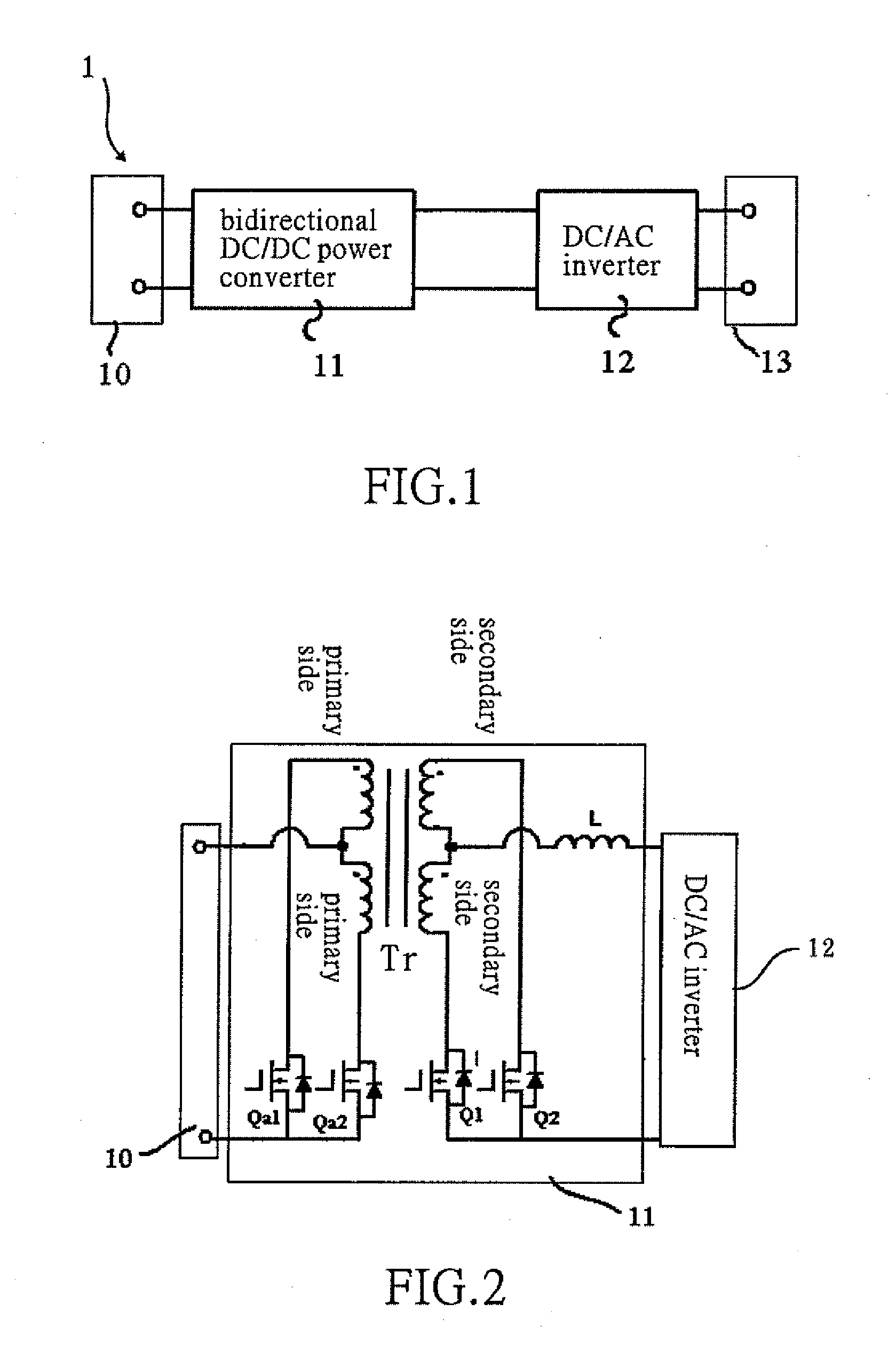
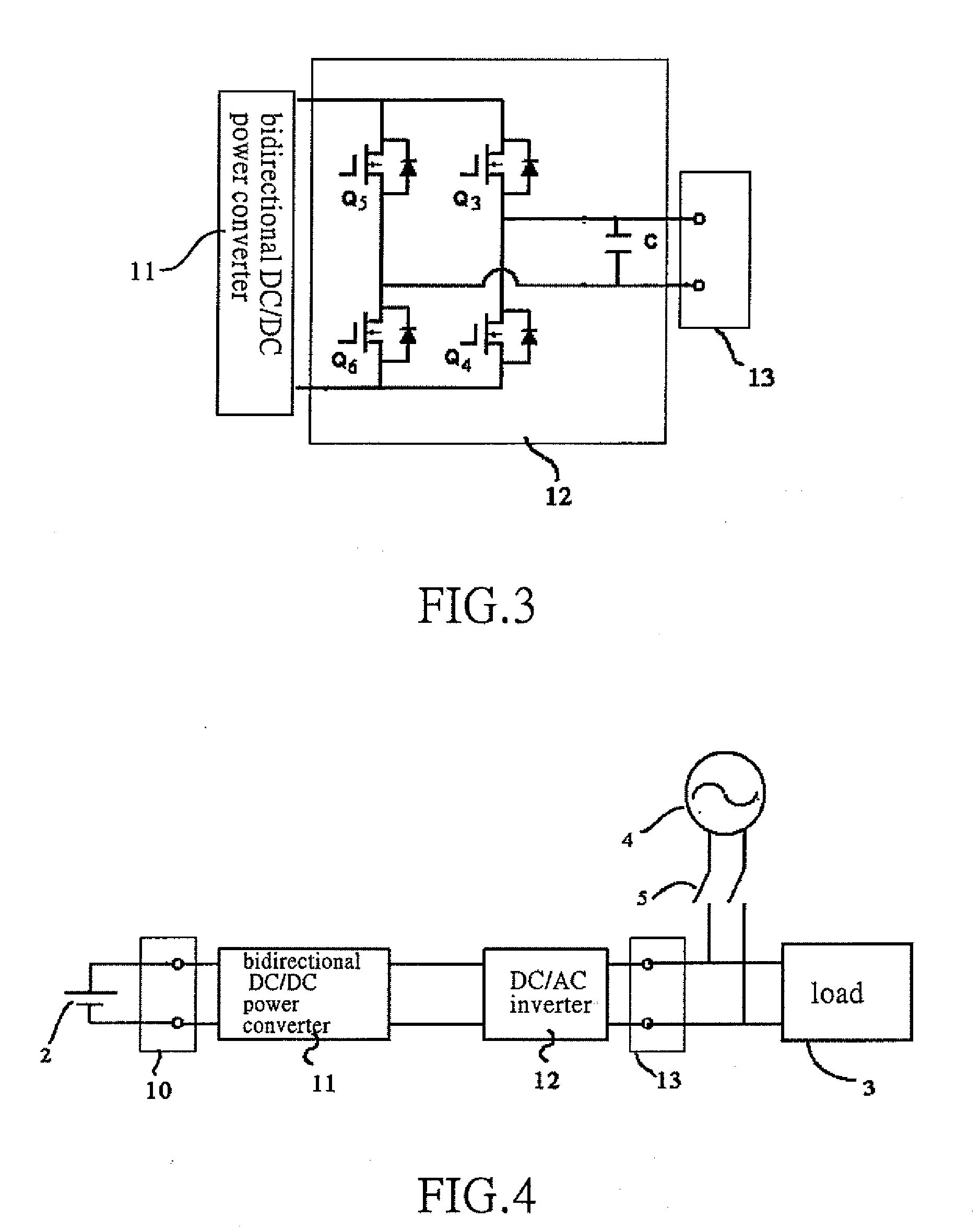
[0027]Turning now to FIG. 1, a schematic circuitry of a bidirectional active power conditioner in accordance with a first embodiment of the present invention is illustrated. The bidirectional active power conditioner 1 includes a DC side 10, a bidirectional DC / DC power converter 11, a DC / AC inverter 12 and an AC side 13.

[0028]Turning now to FIG. 2, a schematic circuitry of the bidirectional DC / DC power converter of the bidirectional active power conditioner in accordance with the first embodiment of the present invention is illustrated. In the first embodiment, the bidirectional DC / DC power converter 11 includes four power electronic switches Qa1, Qa2, Q1, Q2, a high-frequency isolation transformer Tr and an inductor L. Each of the power electronic switches Qa1, Qa2, Q1, Q2 consists of a power switch element and a diode which are connected in anti-parallel relationship. The power electronic switches Qa1, Qa2 are located at a primary side of the high-frequency isolation transformer T...


PUM


Abstract

A bidirectional active power conditioner includes a DC side, a bidirectional DC/DC power converter, a DC/AC inverter and an AC side. The DC side electrically connects with a DC source while the AC side electrically connects with a load and an AC source. The bidirectional DC/DC power converter is controlled via high-frequency pulse width modulation (PWM) switching so as to generate a predetermined DC voltage or DC current while the DC/AC inverter is controlled to convert the predetermined DC voltage or DC current into a predetermined AC voltage or AC current.

Description

BACKGROUND OF THE INVENTION[0001]1. Field of the Invention[0002]The present invention relates to a bidirectional active power conditioner. Particularly, the present invention relates to the bidirectional active power conditioner including a bidirectional DC / DC power converter and a DC / AC inverter connected thereto. More particularly, the present invention relates to the bidirectional active power conditioner using a high-frequency pulse-width-modulation (PWM) switching and controlling the bidirectional DC / DC power converter to generate a predetermined DC voltage or DC current, and further using a low-frequency DC / AC inverter to convert the DC voltage or DC current into a predetermined AC voltage or AC current, so as to enhance the power quality and to improve the power characteristics of the AC loads.[0003]2. Description of the Related Art[0004]Generally, active power conditioners are widely used to enhance the power quality and to improve the power characteristics of the AC loads. ...

Claims


Application Information

Patent Timeline
Patent Type & Authority Applications(United States)
IPC IPC(8): H02M3/335H02J9/00H02M3/00
CPCH02J7/35H02J9/062H02M3/33584Y02B70/1475H02M3/3378H02M2001/007Y02B10/72H02M3/33592H02M1/007Y02B10/70Y02B70/10
Inventor FENG, YA-TSUNGWU, CHIN-CHANGCHOU, HUNG-LIANG
Owner ABLEREX ELECTRONICS CO LTD
Why Eureka
Try Eureka