Bearing monitoring method

Inactive Publication Date: 2008-03-13
ISOTECH OF ILLINOIS +1
View PDF10 Cites 24 Cited by
  • Summary
  • Abstract
  • Description
  • Claims
  • Application Information

AI Technical Summary

Benefits of technology

[0011]It is an objective of the present art to claim and disclose an improvement on the prior art and present viable solutions to the disadvantages of the prior art, including increased reliability of and reduction of energy consumed by roller assemblies and conveyor systems of the prior art.
[0012]It is a further objective of the present art to claim and disclose a method of monitoring the improved bearing isolator in all its embodiments. In this method, the improved bearing isolator may be used as an indicator in connection with a detector system that collects operational data useful in operating the equipment associated with the improved bearing isolator and cooperatively engaged with the improved bearing isolator. The disclosed method may also be used for predictive and preventative maintenance of the improved bearing isolator and any equipment associated or systematically engaged therewith.
[0013]One embodiment of the present invention as illustrated in FIGS. 3, 4A-4C, 6, and 7 is a non-contacting, non-wearing, and non-energy consumptive sealing system that provides adequate protection for primary bearings as may be found in the prior art and particularly those primary bearings used in combination with conveyor roller bearings as found in the prior art. In a first embodiment of the present invention, the bearing seals of the conveyor rollers of the prior art may be replaced with the present art. In this first embodiment, the improved bearing isolator is a substitute for lube containment shields, and the improved bearing isolator will not wear or degrade in use. Since the roller housing rotates around a stationary shaft, high quality and long lasting grease lubricant centrifugates (i.e., migrates through and by centrifugal acceleration) during rotation to the inner track of the outer race of the primary bearing and interacts with the rolling components of the primary bearings. In the embodiments disclosed, at all times there will be no frictional engagement with the sealing components or the improved bearing isolator assemblies.

Problems solved by technology

Any one of the seals or bearings could severely degrade and cause the system to shut down.
A stalled roller may put undue strain on the belt being used for holding the product, and when a bearing grinds to a halt, the resulting heat produced from the increased friction may initiate combustion of various combustible materials in and around the bearing location.
As soon as wear occurs, sealing efficiency degrades so as to be completely ineffective.
Reliability of the system suffers because of the very large number (as calculated above) of wearing and vulnerable components.
The prior art contacting seals are prone to wear and are energy consumptive because of the frictional drag inherent in their design.
Typical environmentally difficult applications are mines, cement works, coal-fired electric utilities and dock installations, among others.
As found by applicant, the prior art fails to achieve the objective.
Given the large numbers of conveyor rollers typically installed and used, it is difficult for operators to be alerted to a primary bearing failure until a secondary event occurs.
Many times, this secondary event is initiation of a smoldering fire or smoke from conveyed materials deposited in close proximity to the conveyor due to the heat often generated from primary bearing failure.
This heat generation that may cause a smoldering fire typically occurs from ferrous metal to ferrous metal contact, as does sparking, both of which are allowed by primary bearing failure.
The typical bearing seal is hidden from external inspection / view and is made of plastic so that it does not only conduct heat poorly but is prone to fail upon rapid heating from either combustion or ferrous metal to ferrous metal contact.
As is well known to those practiced in the art, ferrous metal to ferrous metal contact (rubbing) may be severe enough to raise the metal temperatures to 2500 degrees Fahrenheit (1370 degrees Celsius) and result in partial or full melting of the primary bearing and the destruction thereof.

Method used


Image

  • Bearing monitoring method
  • Bearing monitoring method
  • Bearing monitoring method

Examples


Embodiment Construction

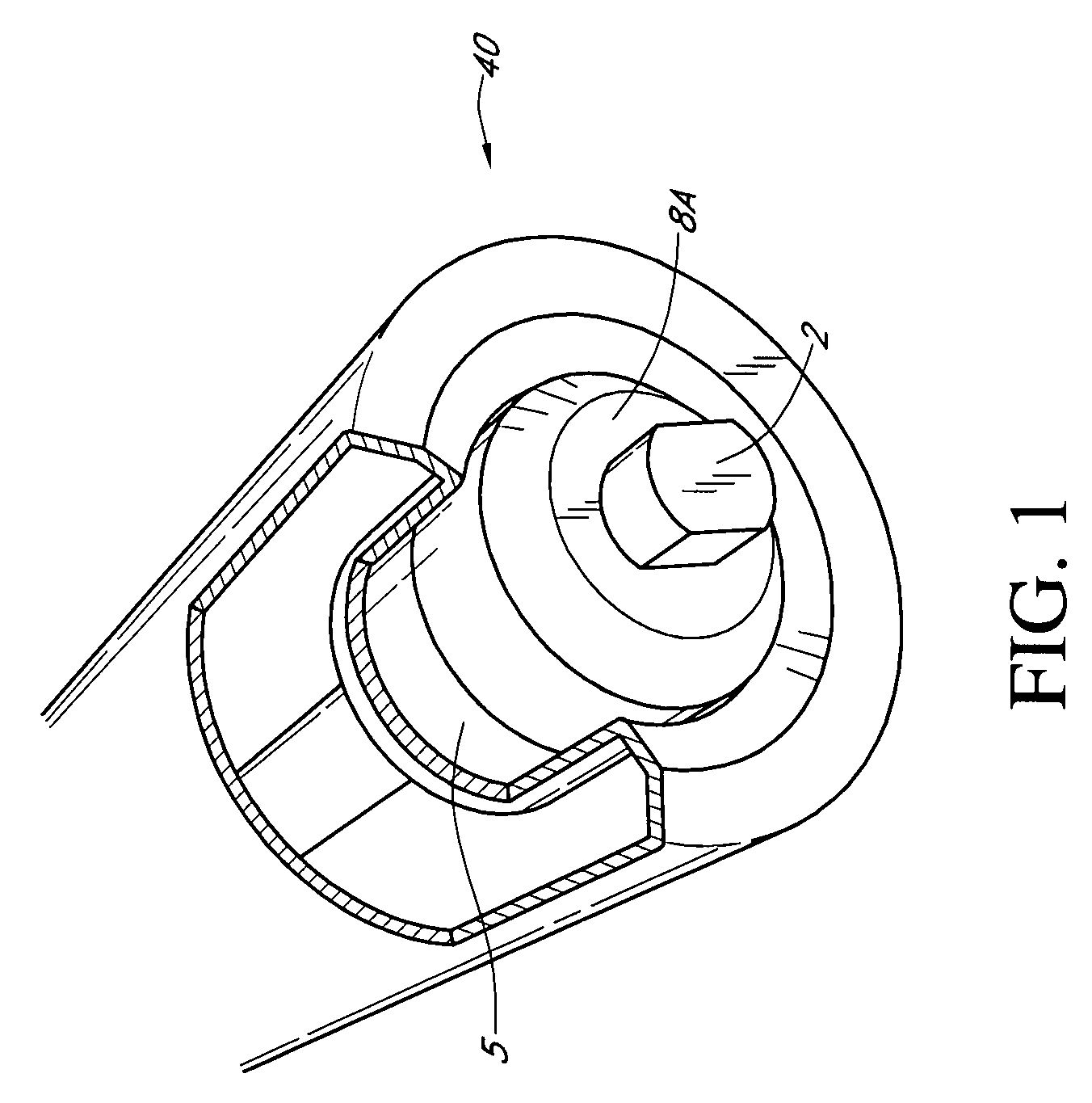
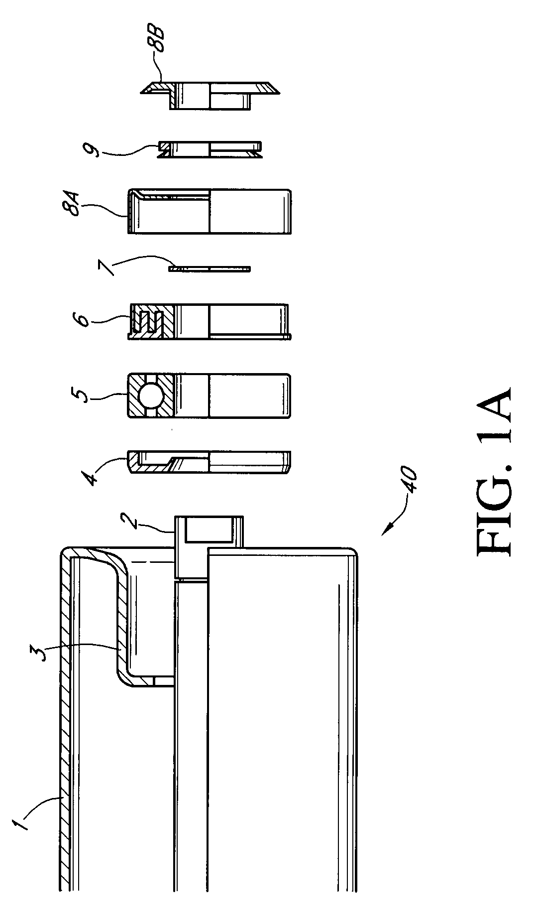
[0048]FIGS. 1 and 1A illustrate the prior art as taught by U.S. Pat. No. 6,802,410 issued to Dyson et al. for “Conveyor Roller Bearing Housing,” which is incorporated by reference herein.

[0049]There are two principal sections shown in FIGS. 1 and 1A of the prior art bearing assembly; one external and one internal. The external section is comprised of a cover 8A and stone guard 8B. As taught by the prior art, the design of the cover 8A and stone guard 8B and the shape of the bearing housing 3, are intended to be self-cleaning when rotating (i.e., centrifugally expel all pollutants). Applicant has not found this to be the case.

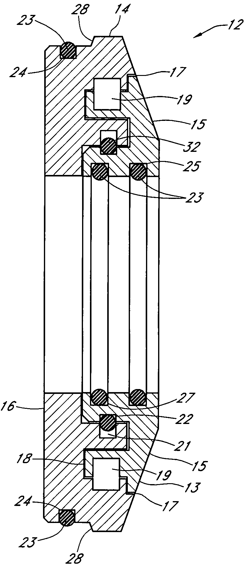
[0050]As illustrated in FIGS. 1 and 1A, the internal section is typically comprised of a triple lip labyrinth seal 6 (sometimes referred to as a lip ring), often made of nylon PA6, which is greased to give further primary bearing 5 protection. In other applications, the labyrinth seal 6 is made from soft, anti-abrasive rubber with a large contact surface that pr...


PUM


Abstract

A method for monitoring a bearing is disclosed. The method involves positioning a non-contacting bearing isolator adjacent a bearing on a piece of rotating equipment so that at least one operating parameter of said bearing is communicated to said bearing isolator; and, positioning an energy detector within range of said bearing isolator so that said energy detector is able to monitor said at least one operating parameter of said bearing by detecting at least one operating parameter of said bearing isolator.

Description

CROSS REFERENCE TO RELATED APPLICATIONS[0001]Applicant claims priority under 35 U.S.C. § 119(e) of provisional U.S. Patent Application Ser. No. 60,842,718 filed on Sep. 7, 2006 which is incorporated by reference herein.FIELD OF INVENTION[0002]The present invention relates to both an improved bearing isolator that may be used alone or in combination with a conveyor roller type arrangement for improved contaminant exclusion in industrial applications and an improved monitoring method and system allowed by said apparatus. When the improved bearing isolator is used in combination with a conveyor roller, the exterior end face of the improved bearing isolator provides an indicator surface for monitoring.STATEMENT REGARDING FEDERALLY SPONSORED RESEARCH OR DEVELOPMENT[0003]No federal funds were used to develop or create the invention disclosed and described in the patent application.REFERENCE TO SEQUENCE LISTING, A TABLE, OR A COMPUTER PROGRAM LISTING COMPACT DISK APPENDIX[0004]Not Applicab...

Claims


Application Information

Patent Timeline
IPC IPC(8): F16C32/00
CPCB65G39/09F16C13/022F16C33/80B65G43/02F16C19/06F16C19/52F16C2233/00F16C2326/58
Inventor ORLOWSKI, DAVID C.HOEHLE, NEIL F.
Owner ISOTECH OF ILLINOIS
Why Eureka
Try Eureka