Process for Operating a Continuous Steam Generator

a technology of continuous steam and process, which is applied in the direction of machines/engines, water feed control, lighting and heating apparatus, etc., can solve the problems of unfavorable performance, inability to calculate the average density p and its change over time p, etc., and achieve the effect of reducing the stress on materials

Active Publication Date: 2008-03-20
SIEMENS ENERGY GLOBAL GMBH & CO KG
View PDF13 Cites 16 Cited by
  • Summary
  • Abstract
  • Description
  • Claims
  • Application Information

AI Technical Summary

Benefits of technology

[0018] With a separate recording of the densities of the flow medium at the entry and the exit of the preheater, feed-water injection and extraction effects can be taken into account in this manner in the preheater and the setpoint value of the feed-water throughflow can be adapted in a simple manner to the operating status of the steam generator.
[0024] The benefits obtained by the invention lie in particular in the fact that, by calculating the feed-water mass flow taking into account the average density of the feed water in the preheater as the correction term, synchronous regulation of the feed-water throughflow through and the heat entry into the evaporator heat surface prevents in an especially simple and reliable manner in all possible operating states of the continuous steam generator fishtailing of the specific enthalpy of the flow medium at the exit of the evaporator heat surface and large temperature variations of the fresh steam generated and thus reduces stresses on materials and increases the lifetime of the steam generator.BRIEF DESCRIPTION OF THE DRAWING

Problems solved by technology

Since however the direct measurement of the feed-water mass flow at the entry of the evaporator heating surface has proved not to be reliable to perform, this measurement is now provided at a suitable upstream point on a medium side, namely at the entry to the preheater.
Especially in the case of a heating change in the preheater however, that is of a non-stationary heat entry into the flow medium within the preheater, for example with a change of load, the calculation of the average density p and its change over time Δp is not possible solely through the approximated use of the entry density.
This could for example occur as a result of the sudden failure of an external preheating path upstream from the preheater.

Method used


Image

  • Process for Operating a Continuous Steam Generator
  • Process for Operating a Continuous Steam Generator
  • Process for Operating a Continuous Steam Generator

Examples


Embodiment Construction

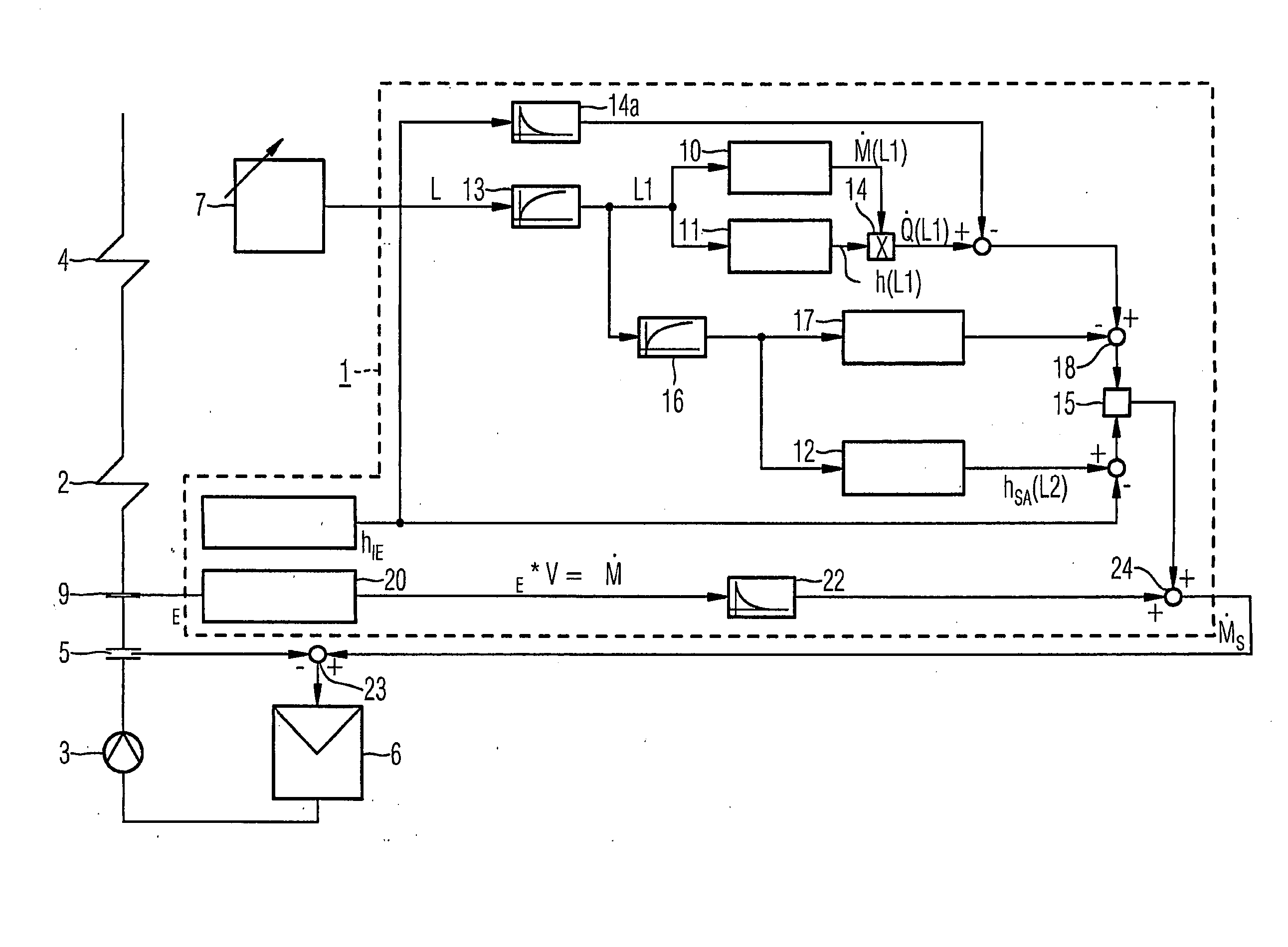
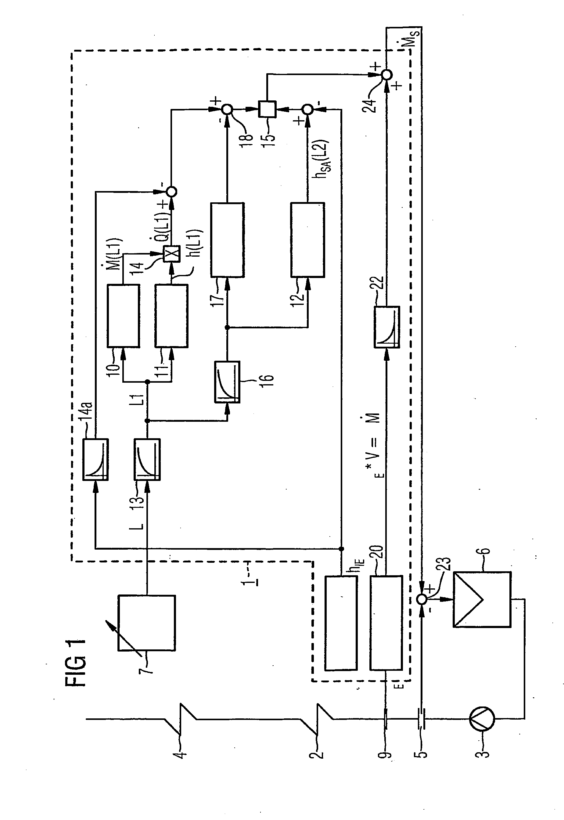
[0032]FIG. 1 shows schematically a device 1 for forming the setpoint value {dot over (M)}s for the feed-water mass flow of a continuous steam generator. The continuous steam generator also features a preheater 2 for feed water, referred to as an economizer, which is located in a gas path not shown in greater detail. On the flow medium side a feed-water pump 3 is connected upstream and an evaporator heating surface 4 downstream of the preheater. A measurement device 5 for measurement of the feed-water mass flow {dot over (M)} through the feed-water line is arranged in the feed-water line routed from the feed-water pump 3 to the preheater 2.

[0033] A controller 6 is assigned to a drive motor at the feed-water pump 3, at the input of which lies the control deviation Δ{dot over (M)} of the feed-water mass flow {dot over (M)} measured with the measurement device 5. The device 1 for forming of the setpoint value {dot over (M)}s for the feed-water mass flow is assigned to the controller 6....


PUM


Abstract

The invention relates to a process for operating a continuous steam generator. The aim of the invention is to provide, with little technical complexity and for any operating state, a synchronous variation of the feed-water mass flow passing through the evaporator heating surface and of the heat input into the evaporator heating surface. To this end, a regulating device for the discharge of feed-water is allocated to a device for adjusting the feed-water mass flow. The control variable of said regulating device is the feed-water mass flow, while its set-point value in relation to the feed-water mass flow depends on the set-point value associated to the power of the steam generator. The actual value of the feed-water density at the entry of the pre-heater is fed to the regulating device for the discharge of feed-water as one of the input values.

Description

CROSS REFERENCE TO RELATED APPLICATIONS [0001] This application is the US National Stage of International Application No. PCT / EP2005 / 053227, filed Jul. 6, 2005 and claims the benefit thereof. The International Application claims the benefits of European Patent application No. 04016248.9 filed Jul. 9, 2004. All of the applications are incorporated by reference herein in their entirety.FIELD OF INVENTION [0002] The invention relates to a process for operating a continuous steam generator with an evaporator heating surface as well as a preheater connected upstream of the evaporator and a device for adjusting the feed-water mass flow {dot over (M)} into the evaporator heating surface. BACKGROUND OF THE INVENTION [0003] In a continuous steam generator the heating of a number of steam generator tubes which together form the gas-tight enclosing wall of the combustion chamber leads to a complete evaporation of a flow medium in the steam generator tubes in one operation. The flow medium—usua...

Claims


Application Information

Patent Timeline
Patent Type & Authority Applications(United States)
IPC IPC(8): F22D7/00
CPCF22B35/10
Inventor BUTTERLIN, AXELKRAL, RUDOLFTHOMAS, FRANK
Owner SIEMENS ENERGY GLOBAL GMBH & CO KG
Why Eureka
Try Eureka