Focus ring and plasma processing apparatus

a plasma processing and focus ring technology, applied in the direction of coatings, chemical vapor deposition coatings, electric discharge tubes, etc., can solve the problems of inability to control the deterioration of the in-surface uniformity of the etching process, etc., to achieve the effect of improving the in-surface uniformity of the plasma processing

Inactive Publication Date: 2008-03-20
TOKYO ELECTRON LTD
View PDF6 Cites 29 Cited by
  • Summary
  • Abstract
  • Description
  • Claims
  • Application Information

AI Technical Summary

Benefits of technology

[0008]In view of the forgoing, the present invention provides a focus ring and a plasma processing apparatus capable of improving in-surface uniformity of plasma processing in comparison with the prior art.
[0017]In accordance with the present invention, there are provided a focus ring and a processing apparatus capable of improving an in-surface uniformity of plasma processing in comparison with the conventional art.

Problems solved by technology

Meanwhile, in a conventional plasma processing apparatus of a type in which an upper electrode is electrically grounded and a plasma is generated by a high frequency power applied to a lower electrode (mounting table), the following problems have conventionally occurred.
That is, when a target substrate is etched in a plasma etching process, for example, an etching rate at a peripheral portion of the target substrate sometimes becomes higher or lower, depending on kinds of etching gases employed, even in case a same focus ring and a same plasma processing apparatus are used, which results in a deterioration of in-surface uniformity of the etching process.
In particular, in case of an etching gas system which does not incur deposition (deposits), the in-surface uniformity may not be controlled by, e.g., adjusting a deposition amount.

Method used


Image

  • Focus ring and plasma processing apparatus
  • Focus ring and plasma processing apparatus
  • Focus ring and plasma processing apparatus

Examples


Embodiment Construction

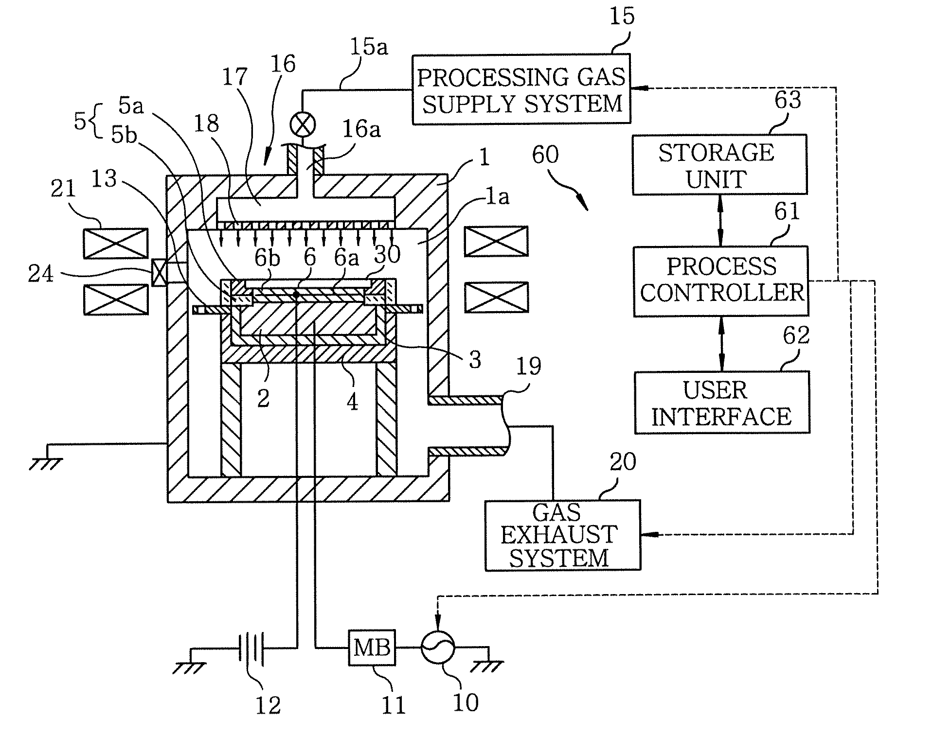
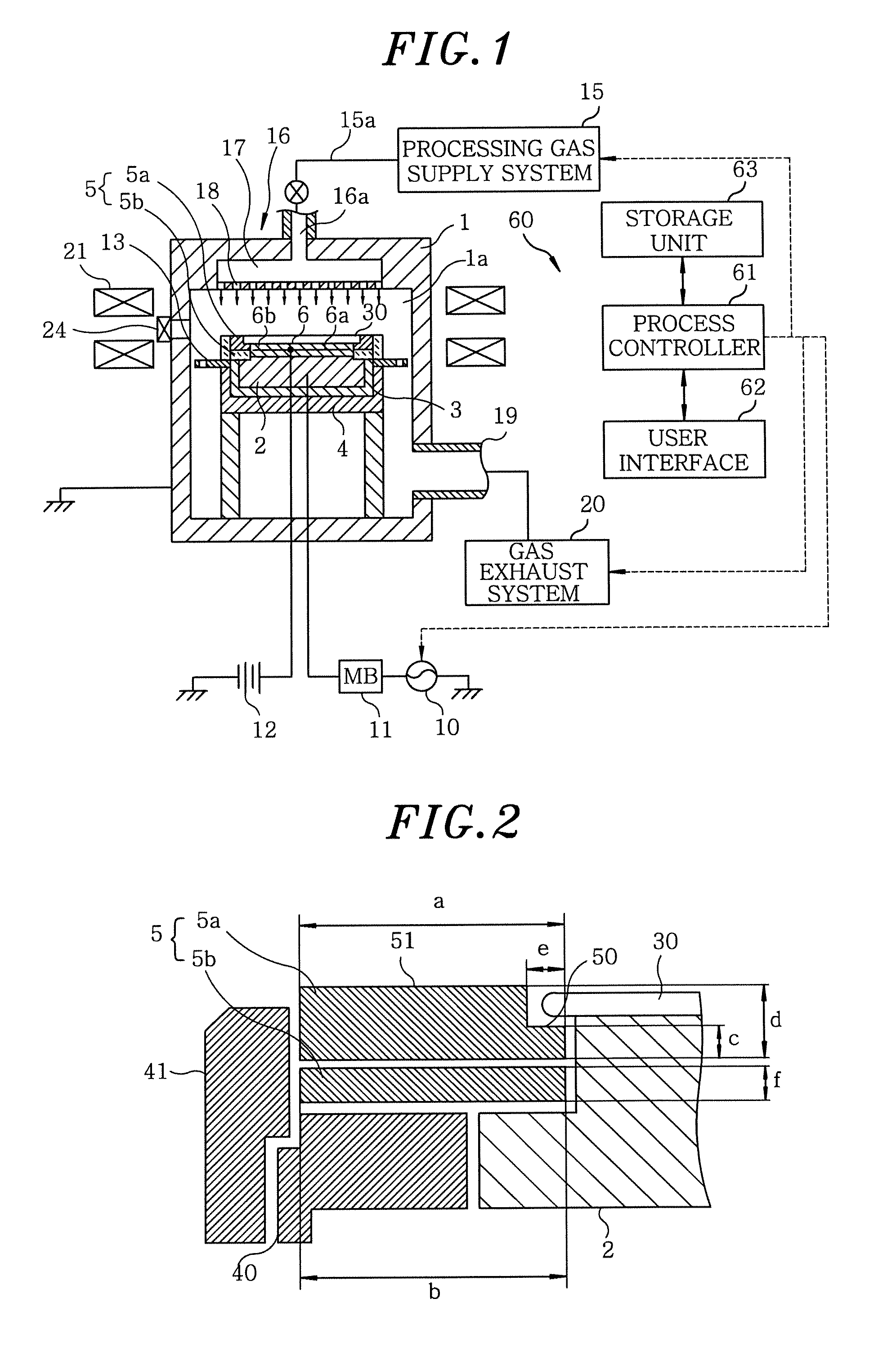
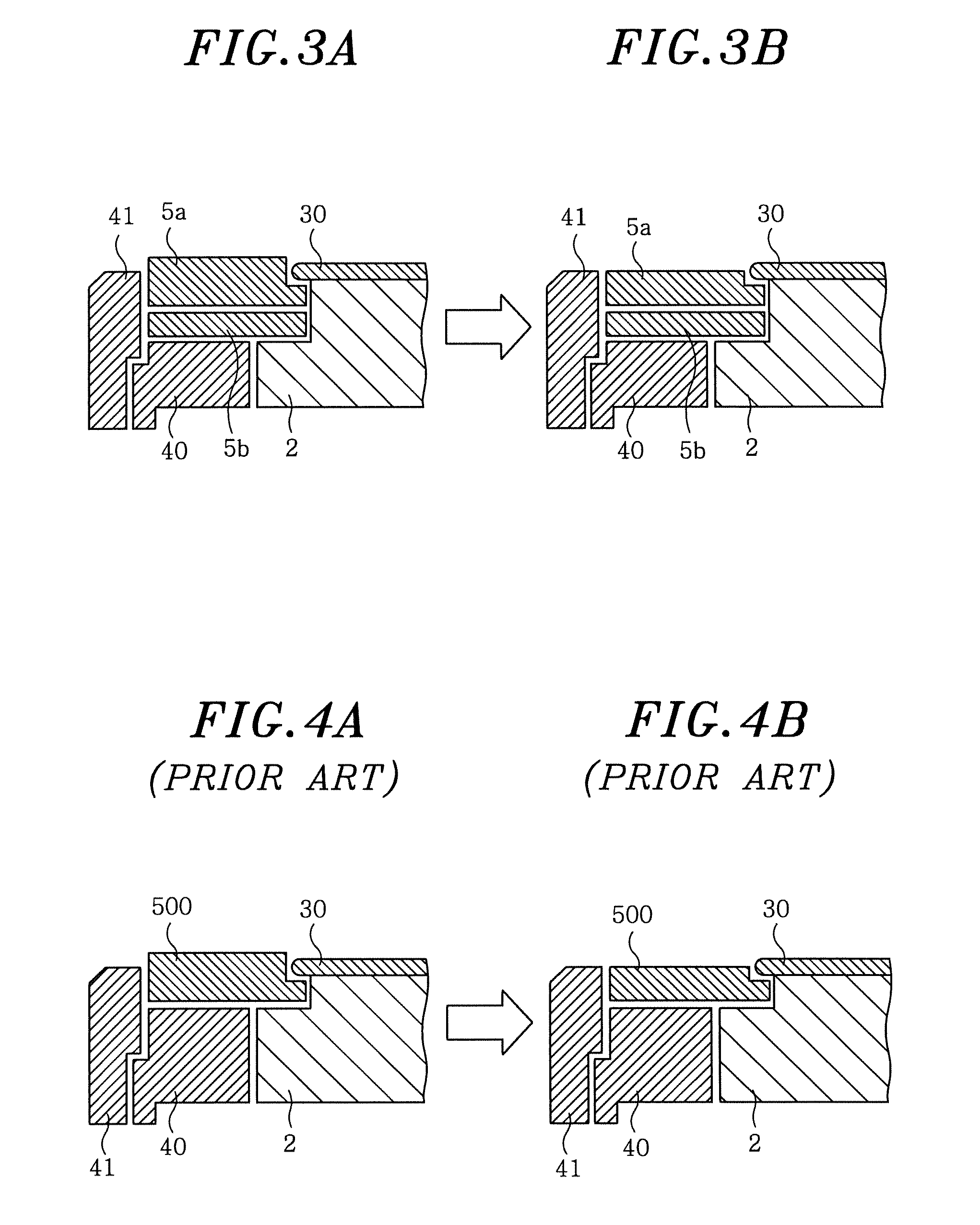
[0023]Hereinafter, embodiments of the present invention will be described with reference to the accompanying drawings that form a part hereof. FIG. 1 shows a schematic configuration of a plasma etching apparatus serving as a plasma processing apparatus in accordance with an embodiment of the present invention. The plasma etching apparatus includes a hermetically sealed processing chamber 1, which is electrically grounded. The processing chamber 1 has a cylindrical shape and is made of, e.g., aluminum. Disposed in the processing chamber 1 is a mounting table 2 for supporting thereon a target substrate to be processed, e.g., a semiconductor wafer 30 in a substantially horizontal manner. The mounting table 2 also functions as a lower electrode, and it is made of, e.g., a conductive material such as aluminum and is supported by a conductive support 4 via an insulating plate 3. Further, an annular focus ring 5 is disposed at the peripheral portion of the top surface of the mounting table...


PUM

PropertyMeasurementUnit
frequencyaaaaaaaaaa
pressureaaaaaaaaaa
thicknessaaaaaaaaaa

Abstract

A focus ring of a plasma processing apparatus for performing a plasma processing on a target substrate to be processed is disposed on the mounting table to surround the target substrate. The focus ring includes a first ring-shaped member made of a conductive material and having a stepped portion at an inner peripheral portion thereof, the stepped portion being positioned lower than a bottom surface of the target substrate mounted on the mounting table and extended below a peripheral portion of the target substrate. The focus ring further includes a second ring-shaped member made of an insulating material and disposed under the first ring-shaped member to be interposed between the first ring-shaped member and the mounting table.

Description

FIELD OF THE INVENTION [0001]The present invention relates to a plasma processing apparatus for performing a plasma process, e.g., a plasma etching process, on a target substrate to be processed and a focus ring employed in the plasma processing apparatus.BACKGROUND OF THE INVENTION [0002]Conventionally, a plasma processing apparatus such as a plasma etching apparatus and the like has been widely used in, e.g., a manufacturing process of fine electric circuits of a semiconductor device.[0003]Well known as such plasma processing apparatus is a so-called parallel plate electrode type plasma processing apparatus, wherein target substrate, e.g., a semiconductor wafer, is mounted on a mounting table in a processing chamber, a plasma processing is carried out by generating a plasma by applying a high frequency power between the mounting table and an upper electrode facing the mounting table.[0004]In such a plasma processing apparatus, there is known a method for improving an in-surface un...

Claims


Application Information

Patent Timeline
Patent Type & Authority Applications(United States)
IPC IPC(8): C23C16/00
CPCH01J37/32642H01J37/32623
Inventor MASUDA, NORIIKI
Owner TOKYO ELECTRON LTD
Why Eureka
Try Eureka