

Hydraulic control circuit
a control circuit and hydraulic technology, applied in mechanical equipment, shock absorbers, transportation and packaging, etc., can solve the problems of affecting the power loss and power consumption of the pump, causing a significant pressure drop, etc., and achieve the effect of simplifying the attenuation
- Summary
- Abstract
- Description
- Claims
- Application Information
AI Technical Summary
Benefits of technology
Problems solved by technology
Method used
Image

Examples
Embodiment Construction
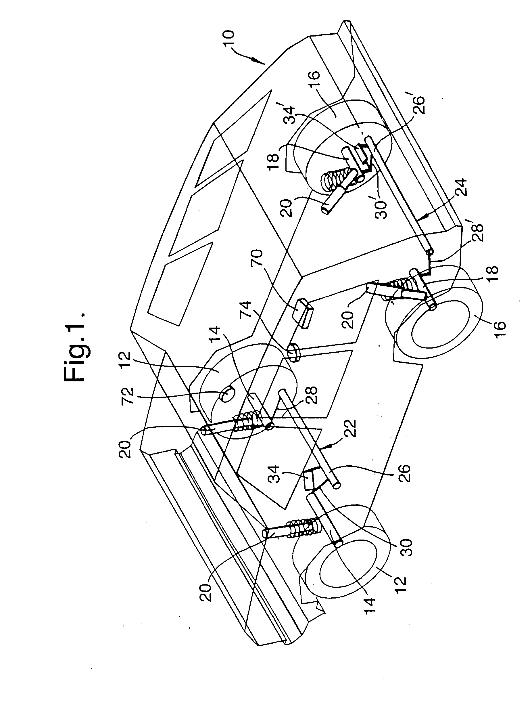
[0014]Referring to FIG. 1, a vehicle 10 is shown schematically and comprises a pair of front wheels 12 each rotatably mounted on an axle 14, a pair of rear wheels 16 each rotatably mounted on an axle 18, and a shock absorbing system 20 associated with each wheel. A portion 22 of a vehicle roll control system is associated with the front wheels 12, and a portion 24 of the vehicle roll control system is associated with the rear wheels 16. The portions 22, 24 are substantially the same but with modifications made solely to allow fitting to the vehicle 10.
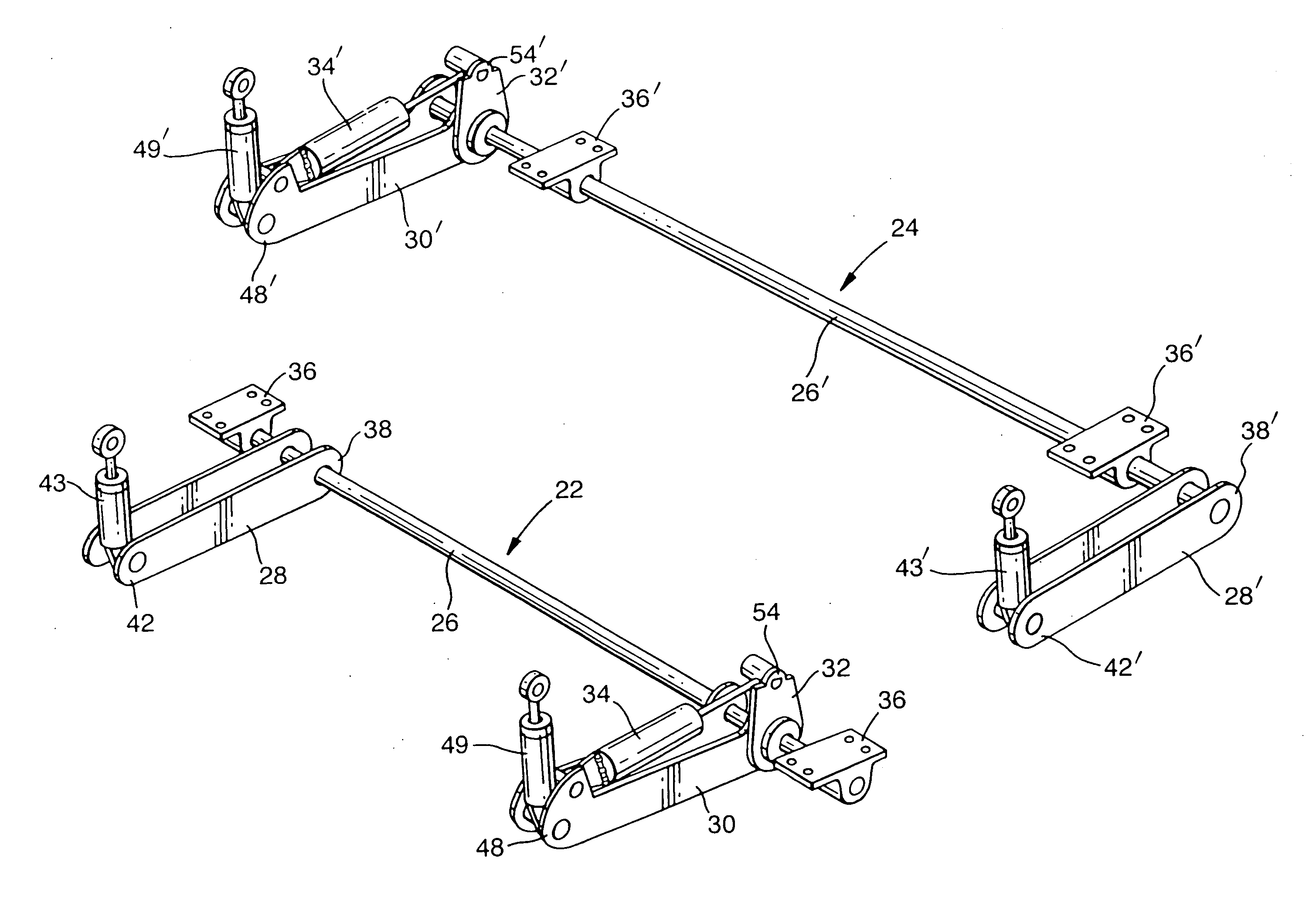
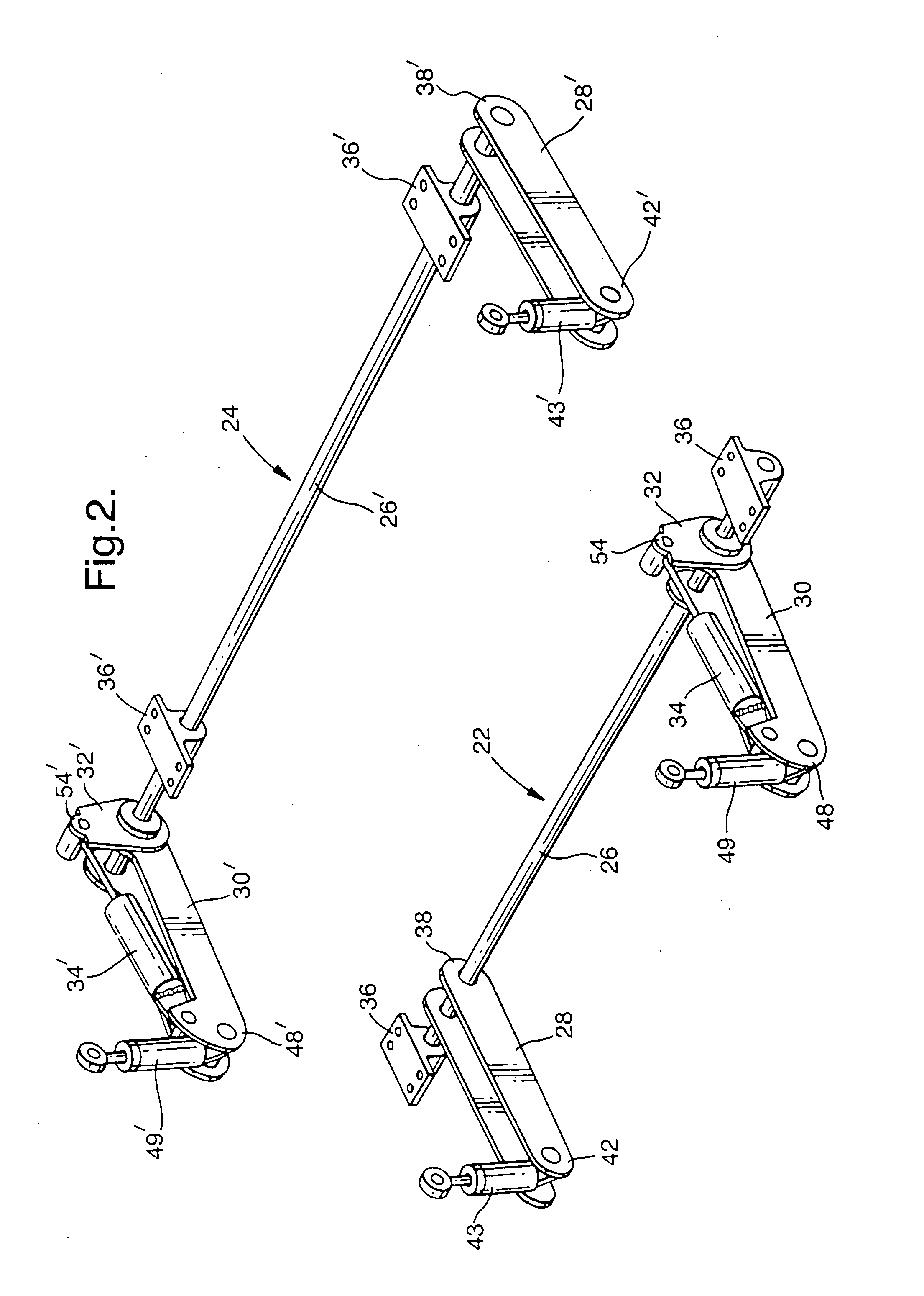
[0015]Referring in more detail to FIGS. 2 to 4, the portion 22 of the vehicle roll control system for the front of the vehicle comprises a torsion bar 26, a first arm 28, a second arm 30, a lever arm 32, and a hydraulic actuator 34. The torsion bar 26 is mounted on the vehicle by a pair of resilient mounts 36 in conventional manner to extend longitudinally between the wheels 12. The first arm 28 (FIG. 3) is fixed at one end 38 by a spl...
PUM
 Abstract
Description
Claims
Application Information