Modular evaporator and thermal energy storage system for chillers

a technology of thermal energy storage and modular evaporators, which is applied in the direction of defrosting, lighting and heating apparatus, and domestic cooling apparatus, etc. it can solve the problems of inferior heat transfer properties, high cost of heat transfer media solutions, and increased electrical consumption, so as to improve heat transfer loop efficiency, reduce cost, and simplify the system

Inactive Publication Date: 2012-03-20
REICH DANIEL +2
View PDF8 Cites 6 Cited by
  • Summary
  • Abstract
  • Description
  • Claims
  • Application Information

AI Technical Summary

Benefits of technology

[0013]According to preferred embodiments of the present invention, a modular evaporator which can be assembled from a number of standard modules is provided. Depending on the requirements, the modular evaporator can be assembled to meet a wide range of design cooling loads. Additionally, the modular evaporator is capable of generating and holding ice for thermal storage purposes, eliminating the need for external ice storage tanks. Furthermore, the heat transfer and thermal storage fluid for the evaporator can simply be water which considerably simplifies the system, lowers the cost, and increases the efficiency of the heat transfer loop.
[0015]Advantages of certain embodiments may include more compact thermal energy storage systems, simplification and reduction in the cost of production of chillers and thermal energy systems, and a considerable increase in the energy efficiency and comfort level of the conditioned environment.

Problems solved by technology

The demand for cooling is usually highest during peak hours when outside temperatures and solar radiation are at their highest levels which results in increased electrical consumption.
First they occupy a considerable amount of floor space for the chiller and the ice storage tanks Secondly, the solutions used as the heat transfer media are generally expensive, toxic, and have inferior heat transfer properties to water which increases the required pumping energy.
And finally, the ratio of ice volume to the full volume of the storage tank is not very high due to the heat exchanger coil occupying a considerable amount of the tank's volume.
The process of calculating the growth of freezing water around multiple tubes is complicated and costly thereby making it impractical for commercial markets.
The heat exchanger design is usually accomplished through an experimental approach which is expensive, time consuming and rarely produces satisfactory results.
Pockets of water can be encapsulated by ice, then, when these pockets freeze, expansion can generate very high pressures which can damage the tubes and / or the shell.
This problem is generally solved by restricting the entire tank water volume from freezing solid which in turn further reduces the average ice storage density and increases the size and weight of the tank required for meeting the cooling demand.
These systems are complicated and expensive.
While this design is potentially capable of increasing thermal energy storage density, it still requires separate spaces for the chiller and the thermal storage unit and requires a heat transfer medium with a freezing temperature below that of water.

Method used


Image

  • Modular evaporator and thermal energy storage system for chillers
  • Modular evaporator and thermal energy storage system for chillers
  • Modular evaporator and thermal energy storage system for chillers

Examples


Embodiment Construction

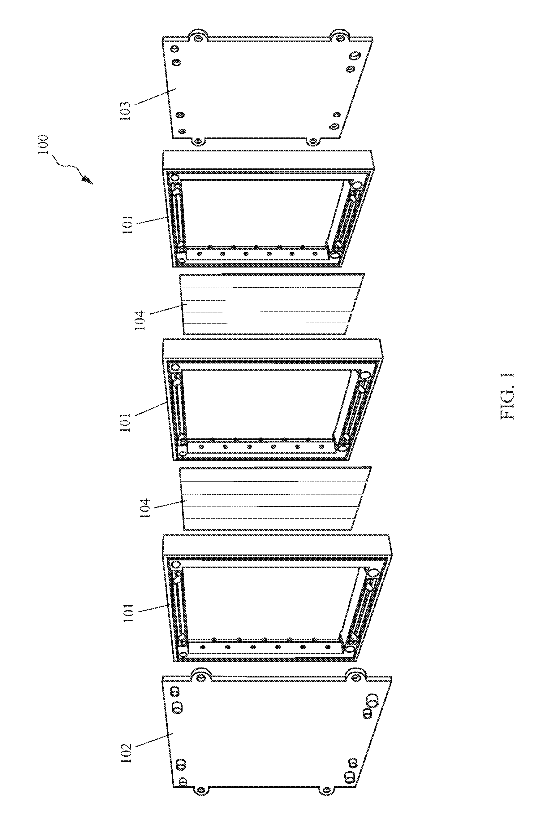
[0032]A preferred embodiment of a modular evaporator 100 incorporating the principles of the present invention is depicted in FIG. 1. As shown, and as will be described in greater detail, the modular evaporator 100 comprises several modules 101 held between respective end plates 102, 103. As depicted, direct expansion cold plates 104 are located between adjacent modules 101 in such a way that they are capable of being compressed by the modules 101. The cold plates 104 are sealed by gaskets.

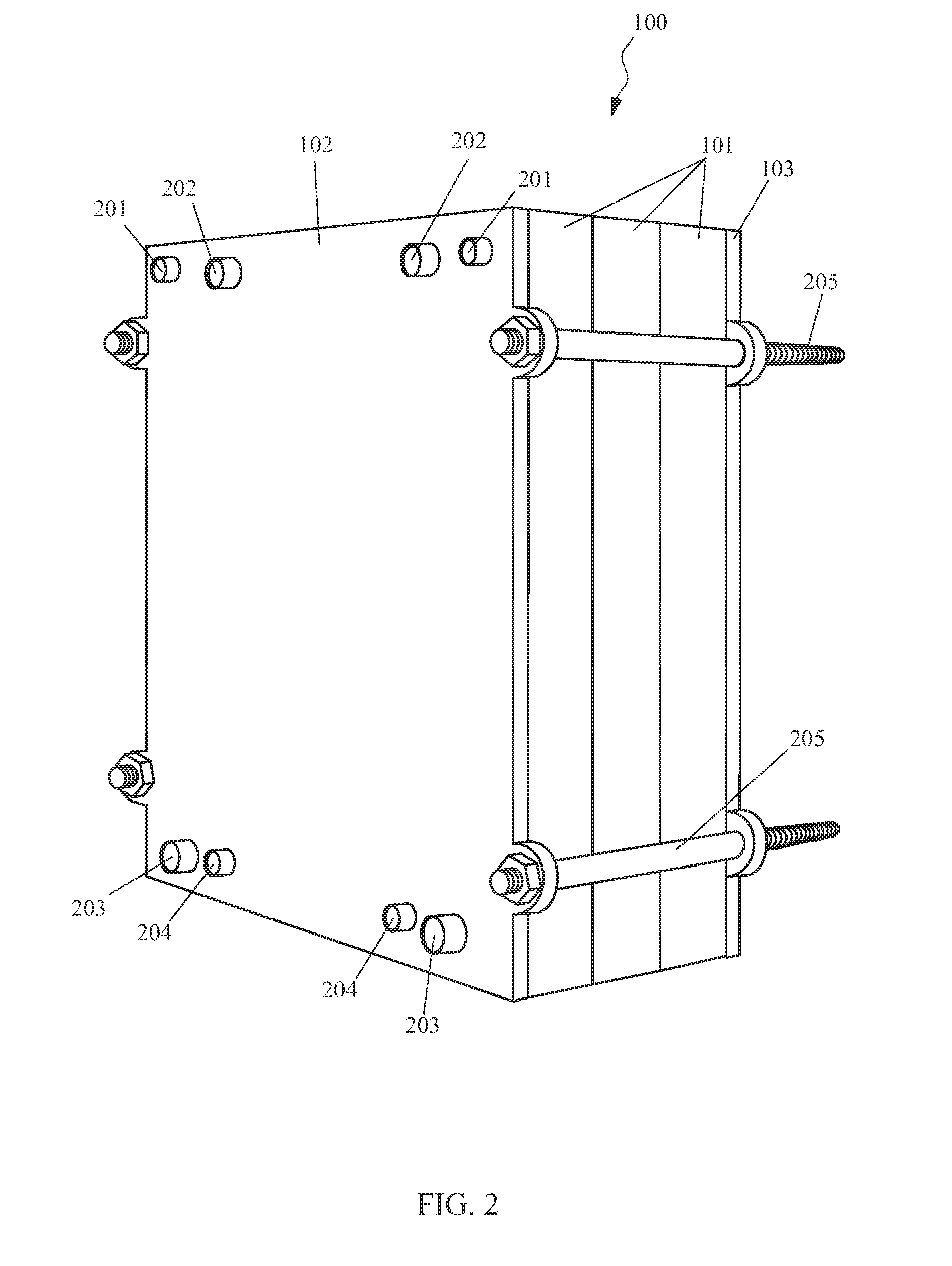
[0033]An assembled modular evaporator 100 is depicted in FIG. 2. The modules 101 and end plates 102, 103 are compressed and fastened together, preferably, by rods 205, forming a water tight vessel. The assembled modular evaporator 100 includes water supply sockets 201 and water return sockets 203, liquid refrigerant sockets 204, and suction sockets 202. FIG. 3 shows the modular evaporator with the end plate 102 detached.

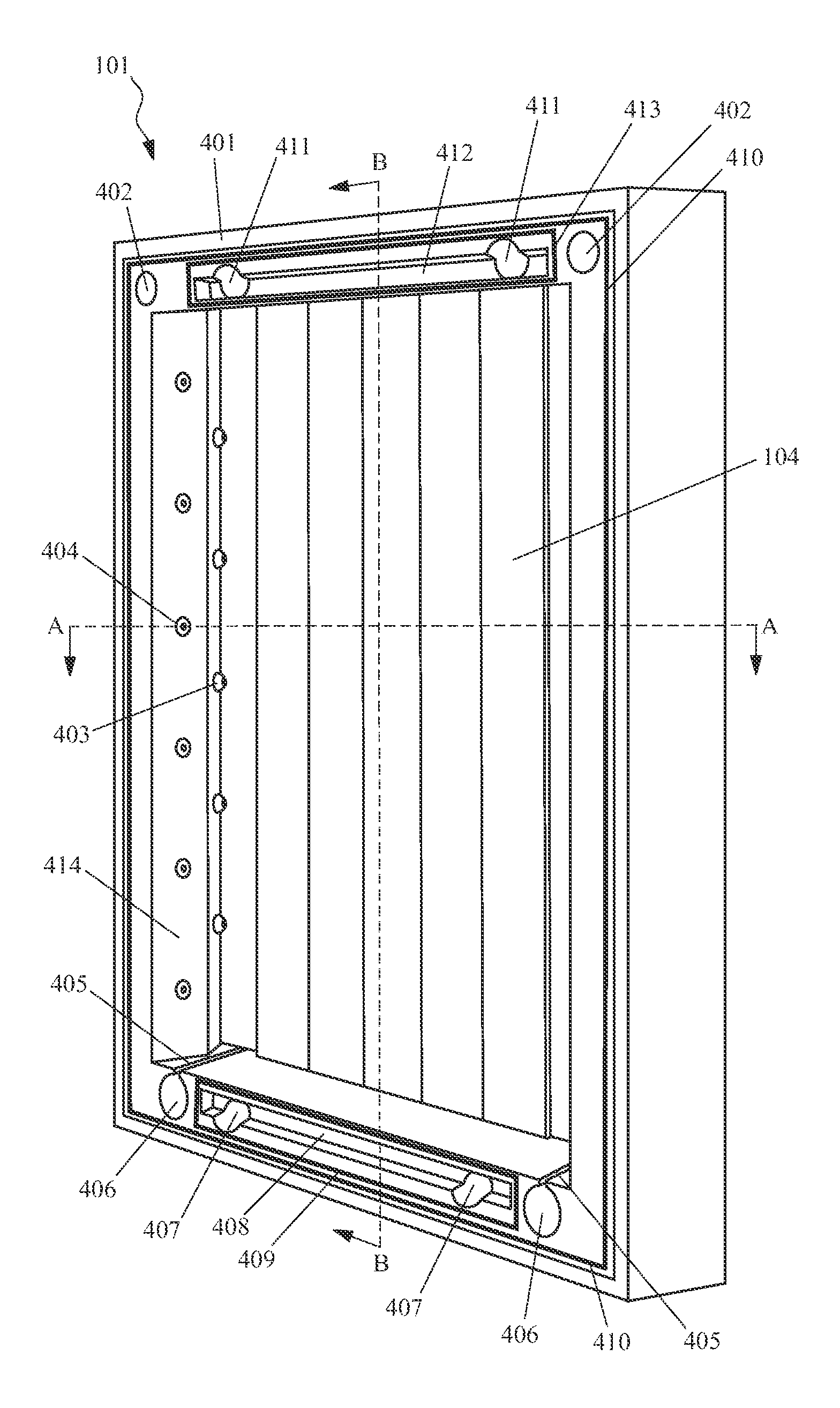
[0034]FIG. 4 depicts a single module 101 in more detail. It is to be understoo...


PUM


Abstract

A modular evaporator which can be assembled from a number of standard modules is provided. Depending on the requirements, the modular evaporator can be assembled to meet a wide range of design cooling loads. Additionally, the modular evaporator is capable of generating and holding ice for thermal storage purposes, eliminating the need for external ice storage tanks. Furthermore, the heat transfer and thermal storage fluid for the evaporator can simply be water which considerably simplifies the system, lowers the cost, and increases the efficiency of the heat transfer loop.

Description

CROSS-REFERENCE TO RELATED APPLICATIONS[0001]The present application is related to and claims priority from prior provisional application Ser. No. 61 / 365,443, filed Jul. 19, 2010, entitled Modular Evaporator and Thermal Energy Storage for Chillers, the contents of which are incorporated herein by reference.FIELD OF THE INVENTION[0002]The present invention relates to cold thermal energy storage systems as well as using such systems to optimize and reduce energy consumption of a building. In particular, this invention relates to a novel modular evaporator and thermal energy storage system for chillers.BACKGROUND[0003]Improving the energy efficiency of building comfort systems has become increasingly more important due to rising energy costs, as well as increased awareness and concern over global warming as a result of humanity's rising consumption of carbon fuels for electrical energy generation, direct burn heating, and domestic hot water appliances. One area where these concerns can...

Claims


Application Information

Patent Timeline
Patent Type & Authority Patents(United States)
IPC IPC(8): F25D17/02
CPCF25B39/02F28F3/083F28F9/026F25B5/02F25B2341/0661F25B2400/21F25B2400/24F25B2600/2513F25B41/385
Inventor REICH, DANIELBURDETT, MICHAEL PAULREICH, VLADIMIR D.
Owner REICH DANIEL
Why Eureka
Try Eureka