Information recording/reproducing device

a recording/recording device and information technology, applied in the direction of maintaining head carrier alignment, nanoinformatics, instruments, etc., can solve the problems of increasing processing costs by a reduction of the minimum width, inability to sufficiently reserve tracking accuracy, and nand-type flash memories and small-size hdds reaching the limit of recording density

Inactive Publication Date: 2008-03-20
KK TOSHIBA
View PDF8 Cites 11 Cited by
  • Summary
  • Abstract
  • Description
  • Claims
  • Application Information

AI Technical Summary

Benefits of technology

[0116] According to the example of the present invention, it is possible to realize the information recording / reproducing device with a high degree of recording density by the highly accurate position control technique.

Problems solved by technology

However, it is pointed out that both the NAND-type flash memories and small-size HDDs will reach the limit of recording density soon.
With respect to the NAND-type flash memory, a processing cost is increased by a reduction of the minimum width of a conductive line.
And with respect to the small-size HDD, it is not possible to sufficiently reserve tracking accuracy.
However, such a ferroelectric recording MEMS memory has not been realized yet although its principle has been conventionally known.
That is, since the electric field from the recording medium can not be detected, it is not possible to perform reading.

Method used


Image

  • Information recording/reproducing device
  • Information recording/reproducing device
  • Information recording/reproducing device

Examples


embodiment

2. Embodiment

(1) MEMS Memory

[0048] There will be described about the MEMS memory to which an example of the present invention can be applied.

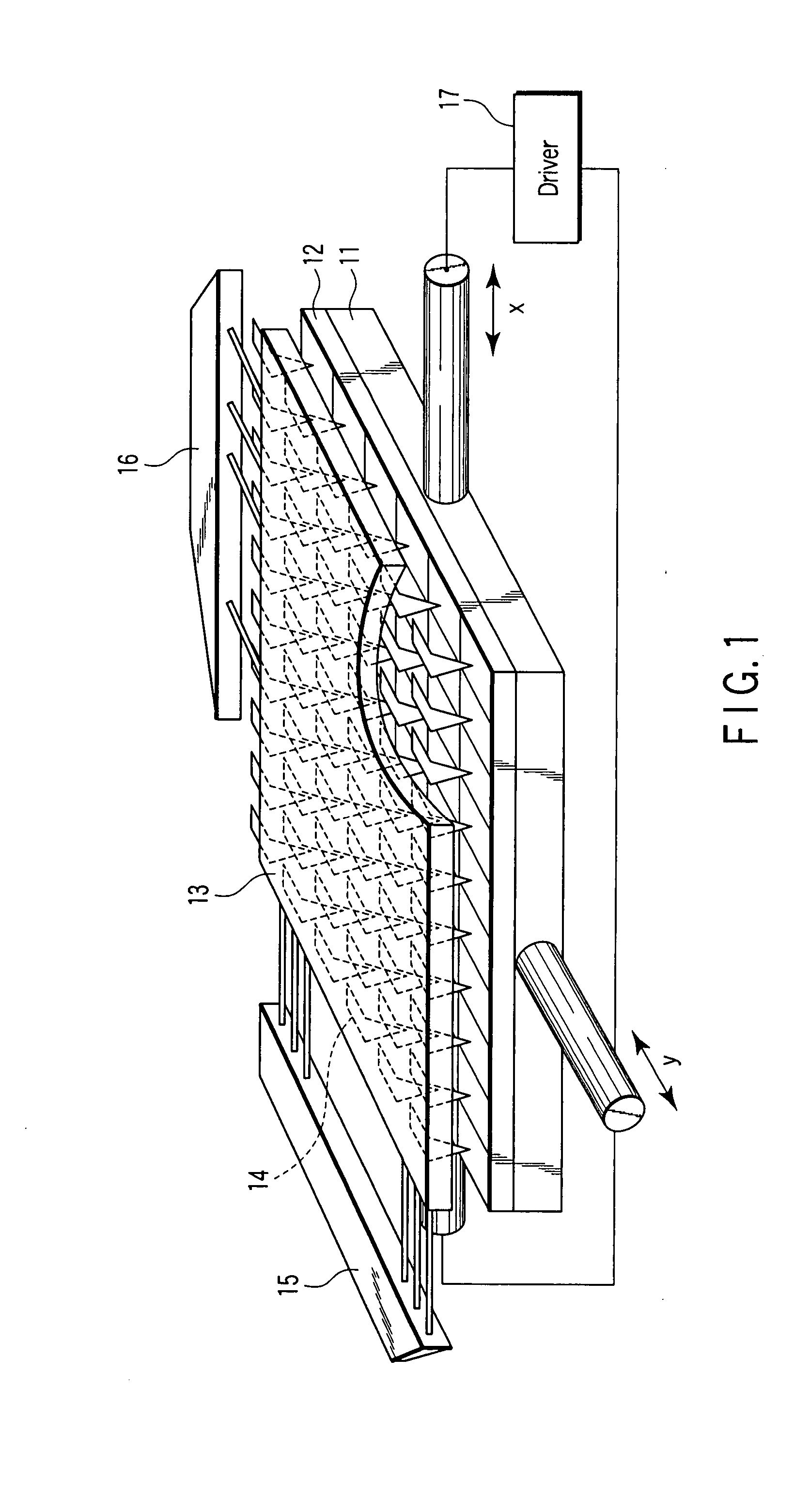
[0049]FIG. 1 shows an outline of the MEMS memory.

[0050] A recording medium 12 is arranged on an XY scanner 11. A probe array is arranged while facing the recording medium.

[0051] The probe array has a semiconductor substrate 13 and a plurality of probes (head) 14 arranged in an array shape at one surface side of the semiconductor substrate 13. Each of the plurality of probes 14, for instance, is comprised a cantilever, and driven by multiplex drivers 15, 16.

[0052] Although the plurality of probes 14 are operable individually by using a micro actuator in the semiconductor substrate 13, there will be described an example in which all of the probes in a batch perform an access to data area of the recording medium with the same operation.

[0053] Firstly, all of the probes 14 are caused to perform reciprocating operation with a fixed period in X...

experiment example

(3) Experiment Example

[0092]FIG. 6 shows an information recording / reproducing device according to an example of the present invention.

[0093] The pitch of the probe array, when supposing that all the probes 14 are aligned with a fixed pitch in the X direction, is set to about 10 μm. At this time, the recording medium 12 performs reciprocating motion in the X direction with a frequency of about 1 kHz, and an amplitude of about 10 μm.

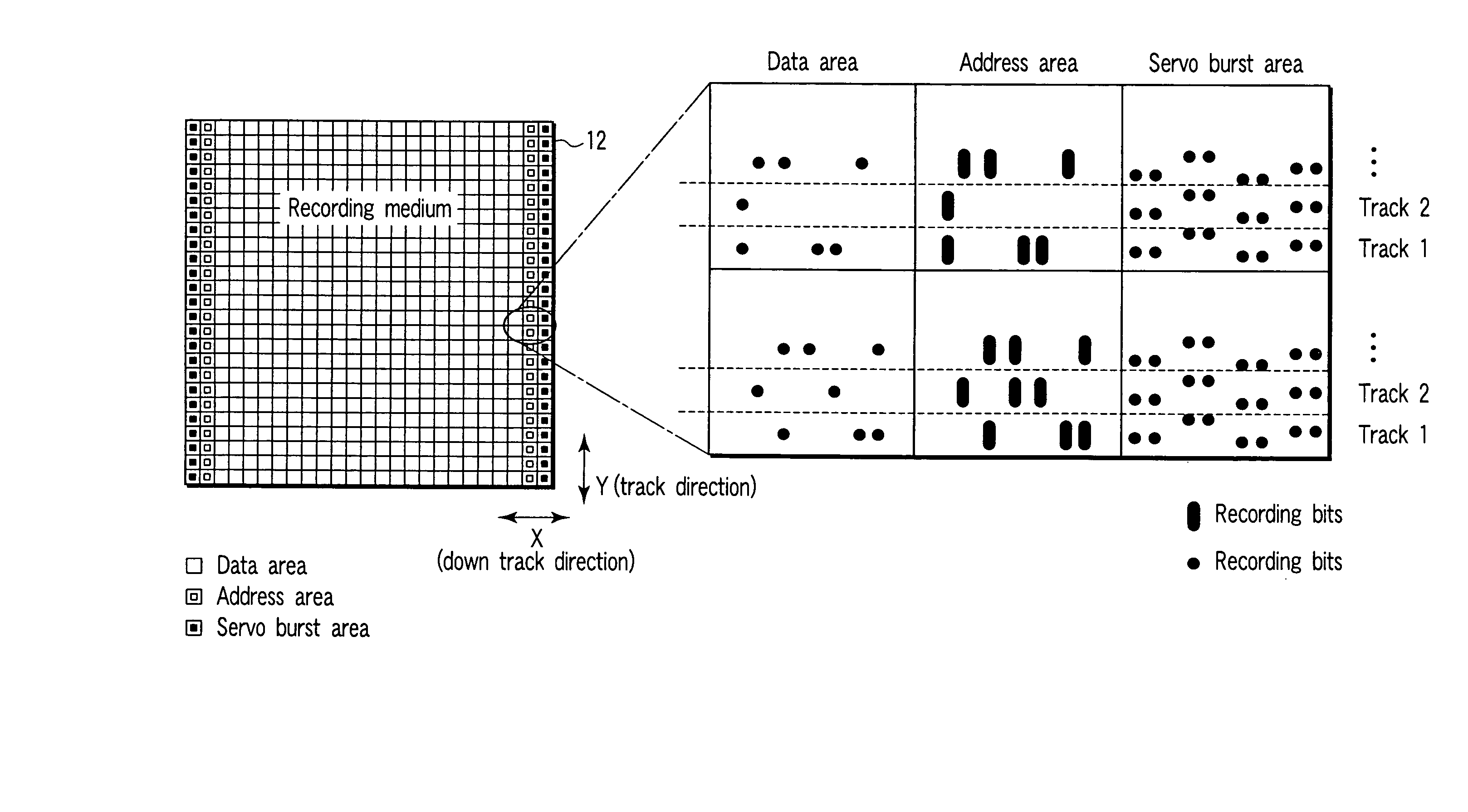
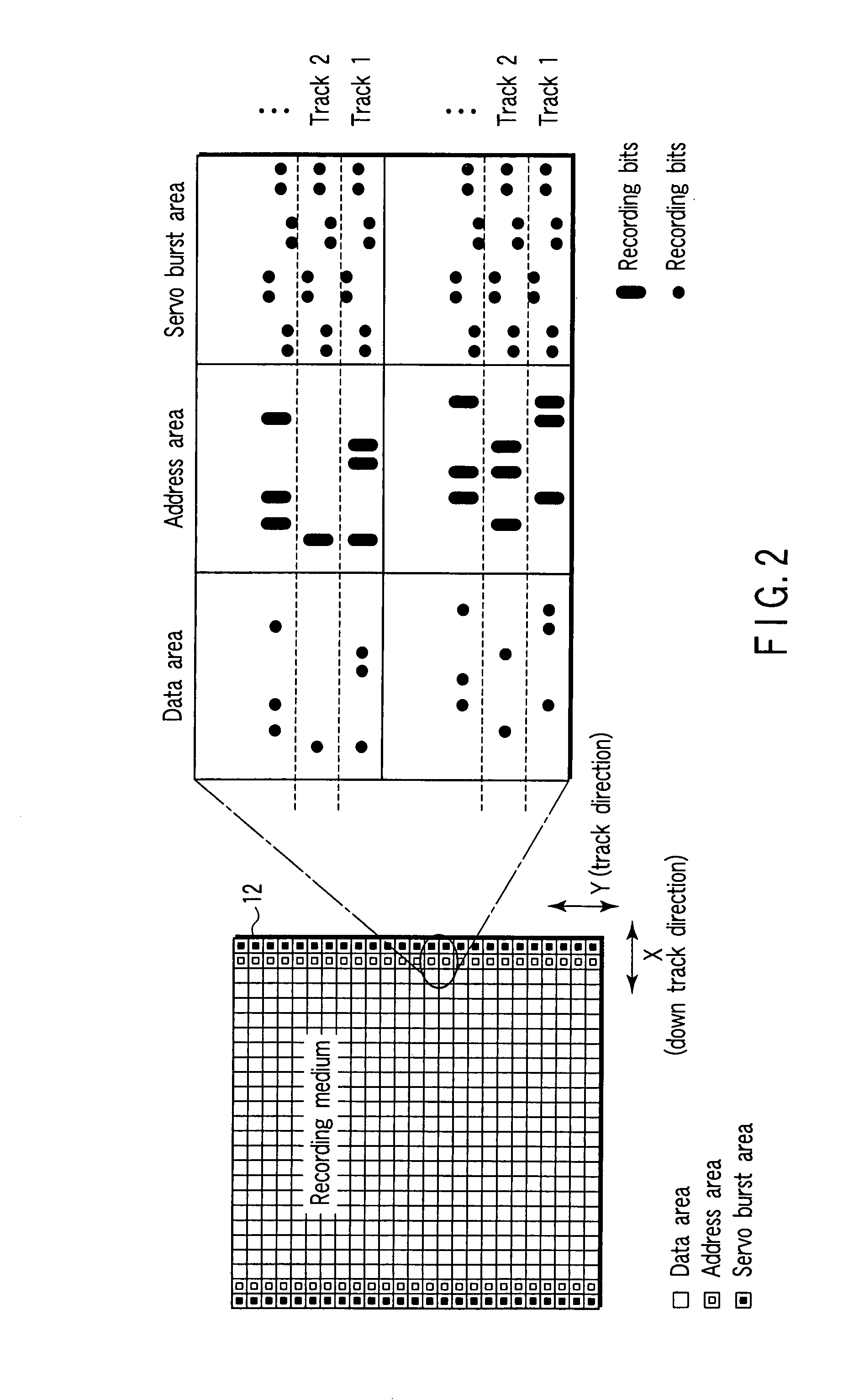
[0094] In the data area, the resistance (data) of the recording bits 26 is read by the probe 14, and at the same time, in the servo burst area, the servo burst signal is read by the probe 14, and position correction of the probe 14 in the Y direction is executed.

[0095] The recording medium 12 is formed by the following manufacturing method.

[0096] As the substrate 21, for instance, a silicon substrate with a vertical size of about 100 mm, a lateral size of about 100 mm, and a thickness of about 1 mm is used.

[0097] The electrode layer 22 made of platinu...


PUM

PropertyMeasurementUnit
sizeaaaaaaaaaa
frequencyaaaaaaaaaa
scan frequencyaaaaaaaaaa

Abstract

An information recording / reproducing device according to an example of the present invention includes first and second heads, a recording medium having a data area from which recording data is read by the first head and a servo burst area from which a servo burst signal is read by the second head, a driver which performs positioning of the second head based on the servo burst signal, and a resistor which covers a surface of the servo burst area and does not cover a surface of the data area. The recording data and the servo burst signal are recorded by a pulse signal.

Description

CROSS-REFERENCE TO RELATED APPLICATIONS [0001] This application is based upon and claims the benefit of priority from prior Japanese Patent Application No. 2006-236741, filed Aug. 31, 2006, the entire contents of which are incorporated herein by reference. BACKGROUND OF THE INVENTION [0002] 1. Field of the Invention [0003] The present invention relates to an information recording / reproducing device. [0004] 2. Description of the Related Art [0005] In recent years, small portable apparatuses have spread worldwide, and simultaneously, demands of the nonvolatile memory with small size and large capacity expand rapidly with extensive progress of a high-speed information transmission network. Above all, in particular, NAND-type flash memories and small-size hard disk drives (HDDs) have evolved in rapid recording densities, resulting in forming great markets. [0006] However, it is pointed out that both the NAND-type flash memories and small-size HDDs will reach the limit of recording densi...

Claims


Application Information

Patent Timeline
Patent Type & Authority Applications(United States)
IPC IPC(8): G11B5/596
CPCB82Y10/00G11B9/1481G11B9/02G11B21/10G11B21/02
Inventor KUBO, KOICHIHIRAI, TAKAHIRAAOKI, SHINYAKOGA, AKIHIROAKIYAMA, JUNICHITAKAKURA, SHINJINAKAMURA, HIROAKI
Owner KK TOSHIBA
Why Eureka
Try Eureka