
Magnetic sheet with stripe-arranged magnetic grains, RFID magnetic sheet, magnetic shielding sheet and method of manufacturing the same

a technology of magnetic grains and magnetic shielding sheets, which is applied in the direction of inking apparatus, mechanical actuation of burglar alarms, instruments, etc., can solve the problems of difficult communication, significant rfid system problems, and inability to communicate, and achieve high magnetic permeability and easy manufacturing

Inactive Publication Date: 2008-03-20
PANASONIC CORP
View PDF1 Cites 136 Cited by
  • Summary
  • Abstract
  • Description
  • Claims
  • Application Information

AI Technical Summary

Benefits of technology

[0020] An object of the present invention is to provide a magnetic sheet with stripe-arranged magnetic grains that has a predetermined stripe pattern of needle-shaped magnetic grains arranged in desirable state so as to have a high magnetic permeability, and is manufactured easily.
[0021] Another object of the present invention is to use the basic configuration of this type of magnetic sheet with stripe-arranged magnetic grains so as to provide a thin RFID magnetic sheet having a high magnetic permeability and flexibility, or an electromagnetic shielding sheet for attachment to a display and that is balanced in terms of electromagnetic wave shielding property and transparency.
[0022] Still another object of the present invention is to provide a manufacturing method of manufacturing these sheets using easy steps and with high performance.

Problems solved by technology

More specifically, there is the drawback that when metal is adjacent to an RFID antenna in the RFID system, communication becomes impossible.
In particular, in the case of using an electromagnetic signal of a high frequency such as 13.56 MHz, problems in the RFID system caused by this drawback are significant.
Therefore, communication becomes difficult.
First, in the case of a magnetic sheet in which ferrite is dispersed in a resin, due to the magnetic sheet having a configuration in which magnetic material (ferrite) is dispersed in the resin, there is an upper limit to the effective magnetic permeability μ. In the case of a configuration using a sintered body of ferrite (ceramic) instead of dispersing ferrite in the resin, the effective magnetic permeability μ increases, but that magnetic sheet becomes brittle because it is a sintered body.
Moreover, the magnetic sheet of that sintered body is also limited in how thin or flexible it can be made.
Thus, obstruction of communication results.
Therefore, it is realistically difficult to use metal magnetic material as the magnetic sheet.
Together with the recent increased use of various electrical equipment and electronic applied equipment, electromagnetic noise interference also is increasing.
These methods can be expected to have an electromagnetic shielding effect in a circuit or power block, but, on the other hand, could not be applied to shielding of electromagnetic waves generated from the front surface of displays such as CRT, PDP, liquid crystal, and EL, because of being opaque.
However, the above-described conventional electromagnetic shielding sheet cannot be said to have sufficient electromagnetic wave shielding properties.

Method used


Image

  • Magnetic sheet with stripe-arranged magnetic grains, RFID magnetic sheet, magnetic shielding sheet and method of manufacturing the same
  • Magnetic sheet with stripe-arranged magnetic grains, RFID magnetic sheet, magnetic shielding sheet and method of manufacturing the same
  • Magnetic sheet with stripe-arranged magnetic grains, RFID magnetic sheet, magnetic shielding sheet and method of manufacturing the same

Examples


first embodiment

[0084] A RFID magnetic sheet according to a first embodiment of the present invention will be described with reference to FIGS. 5A and 5B as well as FIGS. 6A and 6B.

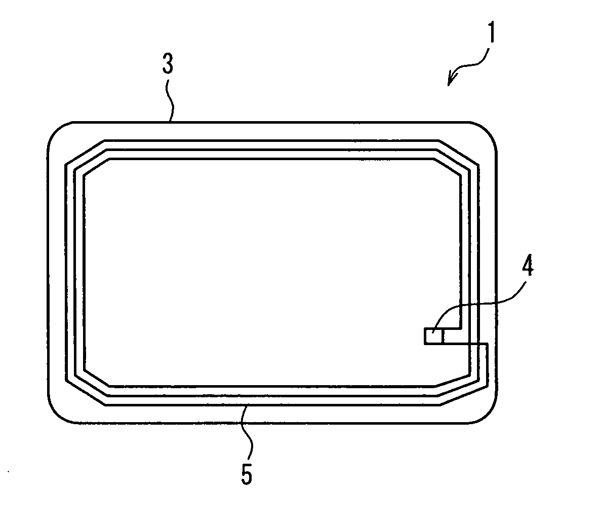
[0085]FIG. 5A schematically shows a top surface configuration of an IC tag 1 in which the RFID magnetic sheet of the present embodiment has been used. FIG. 5B schematically shows the cross-sectional configuration in the state in which an RFID magnetic sheet 2 has been attached to the IC tag 1.

[0086] The IC tag 1 includes a card 3 that is the base substance, an IC chip 4 arranged on the card 3, and a coil antenna (antenna coil for RFID use) 5 connected electrically to the IC chip 4. This IC tag 1 is used as a non-contact type IC card, a unique ID number is stored in the memory of the IC chip 4, and it is possible to store various information in that memory. The IC chip 4 has a built-in CPU and memory, and can perform code processing, authentication, and storage.

[0087] The RFID magnetic sheet 2 of the present embodiment...

second embodiment

[0140] The electromagnetic shielding sheet according to a second embodiment of the present invention will be described with reference to FIG. 18 and FIG. 19. FIG. 18 is a plan view schematically showing the upper surface configuration of an electromagnetic shielding sheet 50 of the present embodiment. FIG. 19 is a plan view showing a partial enlargement of the electromagnetic sheet 50 shown in FIG. 18. The structural elements of the electromagnetic shielding sheet 50 is the same as the magnetic sheet 2 of the first embodiment, and, therefore, identical elements will have the same reference numerals.

[0141] The electromagnetic shielding sheet 50 of the present embodiment includes a resin film 11, a water-repelling layer 12 formed on the resin film 11, and a magnetic lattice 51 made of needle-shaped magnetic grains 15 formed in the water-repelling layer 12. In the water-repelling layer 12 is formed a region having a lattice-shaped pattern (lattice region) 52 exposed by the resin film ...


PUM

PropertyMeasurementUnit
Lengthaaaaaaaaaa
Widthaaaaaaaaaa
Translucencyaaaaaaaaaa

Abstract

A water-repelling layer is formed on a resin film, and a stripe pattern region is formed so as to be positioned within a surface region of the water-repelling layer and so as to be relatively hydrophilic with respect to water repellency of the water-repelling layer. A magnetic stripe pattern is formed of needle-shaped magnetic grains oriented and aggregated in the stripe pattern region. The needle-shaped magnetic grains are arranged in a desirable state in a predetermined stripe pattern, with a high magnetic permeability and a magnetic sheet with stripe-arranged magnetic grains that is thin and flexible is obtained.

Description

BACKGROUND OF THE INVENTION [0001] 1. Field of the Invention [0002] The present invention relates to a magnetic sheet with stripe-arranged magnetic grains in which magnetic grains are arranged in a predetermined stripe-shaped pattern such as a linear or lattice-shaped pattern. In addition, the present invention relates to an RFID magnetic sheet used in an RFID (Radio Frequency Identification) system and an electromagnetic shielding sheet used in display devices etc., which are application examples thereof. [0003] 2. Description of Related Art [0004] Conventionally, there are known applications, such as an RFID magnetic sheet or an electromagnetic shielding sheet, for a thin magnetic sheet in which a magnetic material layer is provided on a flexible substrate. [0005] First, the conventional RFID magnetic sheet will be described. In recent years, it is becoming more common to utilize an RFID system, which is an automatic recognition technology that uses an electromagnetic field of a s...

Claims


Application Information

Patent Timeline
IPC IPC(8): B32B5/00B41J31/14G08B13/22
CPCG06K19/07749Y10T428/32Y10T428/24355G06K19/07771
Inventor NAKATANI, SEIICHIYAMASHITA, YOSHIHISAICHIRYU, TAKASHIHIRANO, KOICHI
Owner PANASONIC CORP
Learn More