Air filter material

a technology of air filter and material, applied in the direction of filtration separation, combustion-air/fuel-air treatment, separation process, etc., can solve the problems of engine failure, sensor malfunction, and inability to obtain the intended air flow rate, etc., to achieve a well-balanced

Active Publication Date: 2008-03-20
DYNIC CORPORATION
View PDF5 Cites 34 Cited by
  • Summary
  • Abstract
  • Description
  • Claims
  • Application Information

AI Technical Summary

Benefits of technology

[0012]To solve the foregoing problems of the conventional technology, it is an object of the present invention to provide a low-cost, nonwoven-based air filter material which exhibits dust penetration resistance, small initial flow resistance, and such capabilities as initial cleaning efficiencies and lives against dust and carbon soot in a well-balanced manner without using splittable fibers.
[0016]The air filter material of the present invention has its own “mean flow pore size”, “minimum pore size”, and “maximum pore size” confined with predetermined ranges. In addition to this, a needle punched nonwoven fabric layer having its areal fiber weight confined to a predetermined range is used as the air inlet layer. Furthermore, a laminate of at least two or more spunlace nonwoven fabric layers having “areal fiber weights”, “mean flow pore sizes”, “minimum pore sizes”, and “maximum pore sizes” confined within respective predetermined ranges is used as the air outlet layer. Consequently, dust penetration resistance and capabilities such as initial cleaning efficiencies and lives against dust and carbon soot are provided in a well-balanced manner without the use of expensive splittable fibers.

Problems solved by technology

If dust-containing air is introduced into cylinders of automobile engines, there can occur the problem of damaging the inner walls of the cylinders and causing an engine failure.
Moreover, when the introduced air is contaminated with carbon soot discharged from diesel engines and the like, sensors for measuring the appropriate flow quantity of air relative to fuel may sometimes malfunction.
A new problem was found, however, that if a large amount of dust is held on an automobile engine air cleaner that uses the air cleaner filter medium described in Japanese Patent Application Laid-Open No.
If the amount of resin applied increases, however, there can occur the problem that an intended rate of air flow cannot be obtained because the carbon soot collection capability drops and the air cleaner filter medium clogs up with dust.
As above, it has been impossible to maintain the dust collection capability, the dust penetration resistance, and the carbon soot collection capability of a nonwoven-based air filter material, such as the air cleaner filter medium described in Japanese Patent Application Laid-Open No.
This has resulted in an increase in manufacturing cost.

Method used


Image

  • Air filter material
  • Air filter material
  • Air filter material

Examples


example 1

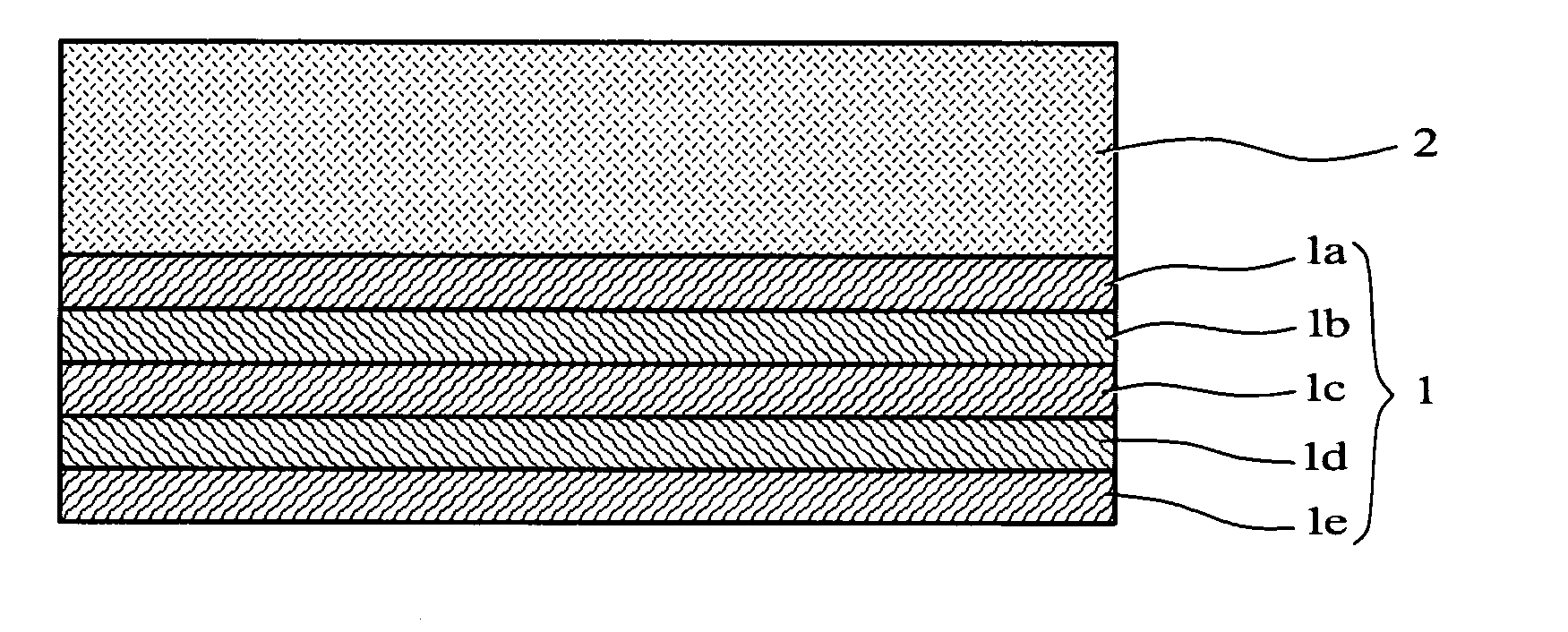
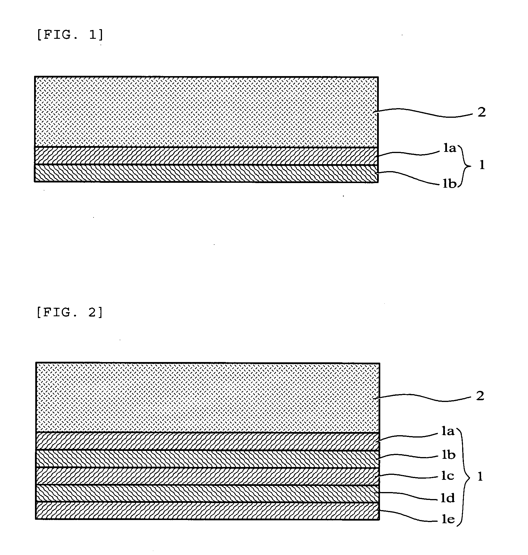
[0050](1a) Initially, a carded web (30 g / m2 in areal fiber weight) containing 30 parts by weight of 0.9-dT polyester staple (51 mm in length, from Teijin Fiber Co., Ltd.) and 70 parts by weight of 1.6-dT polyester staple (51 mm in length, from Teijin Fiber Co., Ltd.) was created, and was made into spunlace nonwoven fabric by hydroentangling. The resulting spunlace nonwoven fabric had a “mean flow pore size,” a “minimum pore size,” and a “maximum pore size” as follows:

[0051]“mean flow pore size”: 63.7 μm,

[0052]“minimum pore size”: 7.1 μm, and

[0053]“maximum pore size”: 144.6 μm.

(1b) Next, a carded web (60 g / m2 in areal fiber weight) containing 1.6-dT polyester staple (51 mm in length, from Teijin Fiber Co., Ltd.) was created, and was made into spunlace nonwoven fabric by hydroentangling. The resulting spunlace nonwoven fabric had a “mean flow pore size”, a “minimum pore size”, and a “maximum pore size” as follows:

[0054]“mean flow pore size”: 48.8 μm,

[0055]“minimum pore size”: 7.9 μm, ...

example 2

[0060]A carded web (75 g / m2 in areal fiber weight) containing 50 parts by weight of 3.3-dT polyester staple (51 mm in length, from Teijin Fiber Co., Ltd.) and 50 parts by weight of 6.7-dT polyester staple (51 mm in length, from Teijin Fiber Co., Ltd.) was created, and was made into nonwoven fabric by needle punching, thereby obtaining an air inlet layer sheet. Except the use of this air inlet layer sheet, the same operations as in example 1 were repeated to obtain an air filter material. The resulting air filter material was 1.70 mm in thickness and 230 g / m2 in weight, and had a “mean flow pore size,” a “minimum pore size,” and a “maximum pore size” as follows:

[0061]“mean flow pore size”: 35.1 μm,

[0062]“minimum pore size”: 3.7 μm, and

[0063]“maximum pore size”: 69.9 μm.

example 3

[0064](3a) Initially, a carded web (30 g / m2 in areal fiber weight) containing 1.6-dT polyester staple (51 mm in length, from Teijin Fiber Co., Ltd.) was created, and was made into spunlace nonwoven fabric by hydroentangling. The resulting spunlace nonwoven fabric had a “mean flow pore size,” a “minimum pore size,” and a “maximum pore size” as follows:

[0065]“mean flow pore size”: 94.4 μm,

[0066]“minimum pore size”: 6.2 μm, and

[0067]“maximum pore size”: 178.0 μm.

(3b) A carded web (70 g / m2 in areal fiber weight) containing 50 parts by weight of 3.3-dT polyester staple (51 mm in length, from Teijin Fiber Co., Ltd.) and 50 parts by weight of 6.7-dT polyester staple (51 mm in length, from Teijin Fiber Co., Ltd.) was created, and was made into nonwoven fabric by needle punching, thereby obtaining an air inlet layer sheet.

(3c) Five pieces of the spunlace nonwoven fabric of the foregoing step (3a) were stacked to form an air outlet layer sheet, and the air inlet layer sheet of the foregoing s...


PUM

PropertyMeasurementUnit
pore sizeaaaaaaaaaa
pore sizeaaaaaaaaaa
pore sizeaaaaaaaaaa

Abstract

An air filter material includes a laminate of an air inlet layer and an air outlet layer, and has a mean flow pore size of 20 μm to 40 μm, a minimum pore size of 2.4 μm to 3.8 μm, and a maximum pore size of 80 μm or less. The air inlet layer is a needle punched nonwoven fabric layer having an areal fiber weight of 55 g / m2 to 100 g / m2. The air outlet layer is a laminated spunlace nonwoven fabric made by laminating at least two or more spunlace nonwoven fabric layers having an areal fiber weight of 20 g / m2 to 60 g / m2, a mean flow pore size of 50 μm to 90 μm, a minimum pore size of 3.0 μm to 10.0 μm, and a maximum pore size of 180 μm or less.

Description

[0001]This application is a Continuation-in-Part of application PCT / JP2006 / 318291 filed on Sep. 14, 2006. The entire disclosure of the prior application is hereby incorporated by reference in its entirety.BACKGROUND OF THE INVENTION[0002]1. Field of the Invention[0003]The present invention relates to an air filter material to be used in an air cleaner for various types of internal combustion engines that run on gasoline, ethanol, light oil, heavy oil, or other fuels, including four-stroke or two-stroke reciprocating engines, rotary engines, and gas turbine engines. In particular, the present invention relates to an air filter material intended for engines of automotive vehicles (such as a motorcycle and a four-wheel car), which has excellent capabilities to collect carbon soot as well as to collect sand and other dusts (see JIS D-1612) and is further capable of suppressing a dust penetration phenomenon which tends to occur under particular conditions.[0004]2. Description of the Rela...

Claims


Application Information

Patent Timeline
Patent Type & Authority Applications(United States)
IPC IPC(8): B32B3/26B01D50/00B01D39/16B01D39/18D04H1/492D04H1/498F02M35/024
CPCB01D39/1623B01D46/521F02M35/024B01D2275/10B01D2239/0659Y10T442/666Y10T442/667Y10T428/249978Y10T442/682Y10T428/249979Y10T428/24998
Inventor UMEZU, NORIOMIZUI, KAZUMASA
Owner DYNIC CORPORATION
Why Eureka
Try Eureka