Microstructure and method of manufacturing the same

Inactive Publication Date: 2008-03-20
FUJIFILM CORP
View PDF2 Cites 15 Cited by
  • Summary
  • Abstract
  • Description
  • Claims
  • Application Information

AI Technical Summary

Benefits of technology

[0008] It is therefore an object of the present invention to provide a microstructure that may be

Problems solved by technology

According to the track etching technique, discrete micropores with a narrow pore size distribution are formed orthogonally to the organic film, but this technique suffered from the problem that the pore density, that is, pore opening area ratio could not be increased to prevent overlapping pores from being generated due to incidence of particles on the film in an overlapping manner when forming tra

Method used


Image

  • Microstructure and method of manufacturing the same
  • Microstructure and method of manufacturing the same
  • Microstructure and method of manufacturing the same

Examples


Example

Examples 1 to 5 and Comparative Example 1

1. Electrolytic Polishing

[0141] A high purity aluminum substrate (manufactured by Sumitomo Light Metal Industries, Ltd.; purity, 99.99 wt %; thickness, 0.4 mm) was cut into samples (area: 10 cm×10 cm) suitable for anodizing treatment. The samples were subjected to electrolytic polishing in an electrolytic polishing solution of the composition indicated below under the conditions of a voltage of 25V, a solution temperature of 65° C. and a solution flow rate of 3.0 m / min. A carbon electrode was used for the cathode. A GP0110-30R unit (Takasago, Ltd.) was used for the power supply. The flow rate of the electrolytic solution was measured with a vortex flow monitor FLM22-10PCW (manufactured by As One Corporation). 85 wt % Phosphoric acid (Wako Pure Chemical660 mLIndustries, Ltd.)Pure water160 mLSulfuric acid150 mLEthylene glycol 30 mL

2. (A) Micropore Formation Through Anodization

[0142] The samples polished as above were anodized under the co...

Example

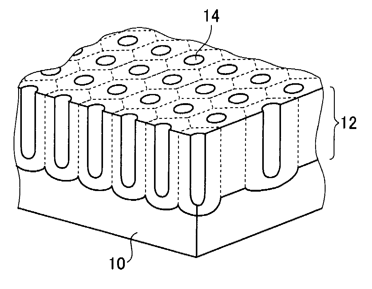
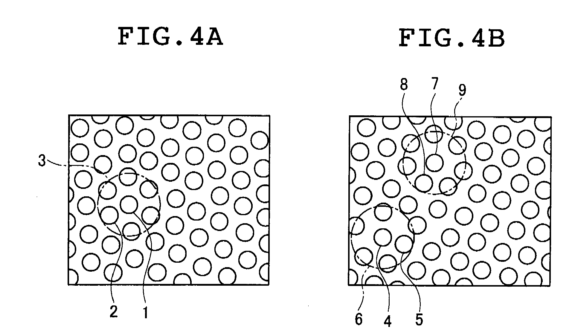
[0147] The microstructures obtained in Examples 1 to 5 and Comparative Example 1 were measured for their degree of ordering and pore opening area ratio. More specifically, their surfaces were photographed with a field emission scanning electron microscope (FE-SEM) at a magnification of 20,000× and the degree of ordering as defined by formula (1):

Degree of Ordering (%)=B / A×100   (1)

(wherein A represents a total number of micropores in a measurement region; and B represents a number of specific micropores in the measurement region for which, when a circle is drawn so as to be centered on a center of gravity of a specific micropore and so as to be of a smallest radius that is internally tangent to an edge of another micropore, the circle includes centers of gravity of six micropores other than the specific micropore), and the pore opening area ratio as defined by formula (2):

Pore opening area ratio (%)=C / D×100   (2)

(wherein C represents a sum of opening areas of the micropores in...

Example

Example 6

[0149] A specific example of use of the microstructure in filter form according to the present invention is described below.

[0150] A slurry of an amorphous silicate material pulverized to an average particle size of 20 nm by a breakdown process and calcium oxide were mixed with a molar ratio of CaO to SiO2 of 0.4. To the mixture was added with stirring a 10-fold weight of water based on the total weight of the material to prepare a slurry. Then, this slurry was placed in an autoclave and subjected to a hydrothermal reaction with stirring at 180° C. for 4 hours to obtain a calcium silicate slurry. The resulting slurry was cooled to 70° C. Acetic acid having a concentration as high as 99.7% which was required for removing calcium oxide in the calcium silicate was added to the slurry and the mixture was stirred for 10 minutes to obtain a solution. The microstructure prepared in Example 1 was immersed in the solution at an immersion temperature of 30° C. for 60 seconds, then ...


PUM

PropertyMeasurementUnit
Fractionaaaaaaaaaa
Fractionaaaaaaaaaa
Timeaaaaaaaaaa

Abstract

Disclosed is a microstructure comprising an aluminum anodized film bearing through micropores, wherein a surface of the microstructure is covered with a protective film for preventing hydration of the aluminum anodized film. The microstructure may be used as a porous alumina membrane filter excellent in filtration rate and its stability with time.

Description

[0001] The entire contents of all documents cited in this specification are incorporated herein by reference. BACKGROUND OF THE INVENTION [0002] The present invention relates to a microstructure and its manufacturing method. [0003] Filter membranes including organic membranes and inorganic membranes are commercialized in the field of microfiltration, and such organic membranes are actually widely used. In most of the organic membranes, pores are not separated from each other and the pore size distribution is relatively broad. Therefore, researches for further improving the accuracy in the separation of a target substance which is the most important filter function have been made in various fields. [0004] In order to solve such problems, a so-called track etching technique is known in which an organic film made of a polymer is irradiated with high energy particles generated in a nuclear reactor, and tracks of the particles through the organic film are etched to form micropores (see T...

Claims


Application Information

Patent Timeline
IPC IPC(8): B32B3/12C25D11/18
CPCC25D11/12C25D11/24C25D11/045B01D67/0065B01D67/0088B01D69/02Y10T428/1234B01D71/02B01D71/024B01D71/025B01D71/027B01D71/34B01D2325/02B01D69/12Y10T428/249953Y10T428/249969Y10T428/24997Y10T428/249974
Inventor HATANAKA, YUSUKETOMITA, TADABUMIHOTTA, YOSHINORIUESUGI, AKIO
Owner FUJIFILM CORP
Why Eureka
Try Eureka