

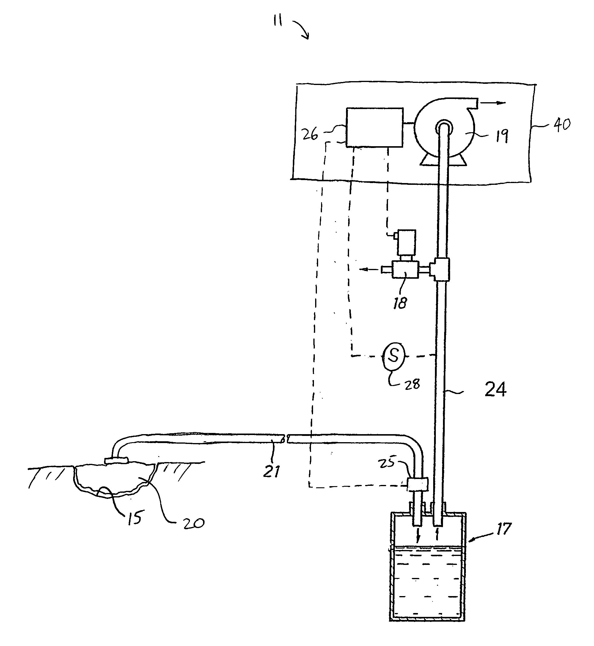
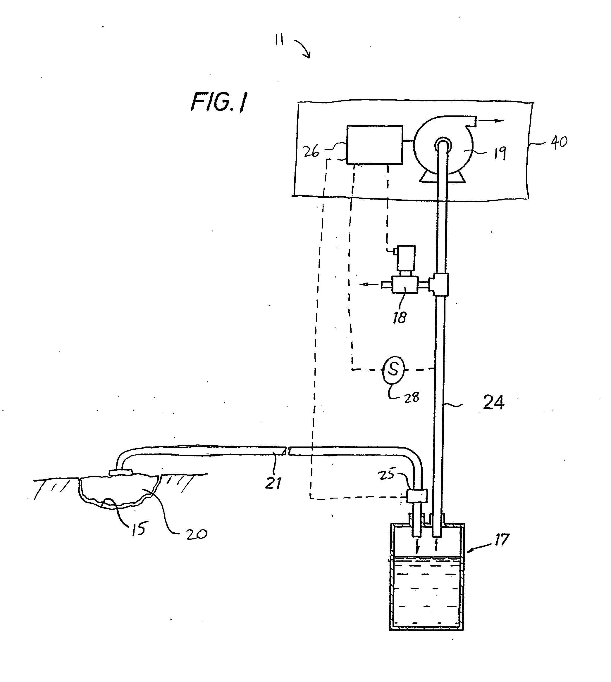
System and method for determining a fill status of a canister of fluid in a reduced pressure treatment system
a technology of a treatment system and a fill status, applied in the field of medical devices, can solve the problems of increasing the possibility of superinfection of wounds, not only painful for patients, but also the problem of open wounds and sores such as decubitis ulcers and those found on the feet of diabetics, so as to reduce the possibility of superinfection and reduce the pressure
- Summary
- Abstract
- Description
- Claims
- Application Information
AI Technical Summary
Benefits of technology
Problems solved by technology
Method used
Image

Examples
Embodiment Construction
[0019] In the following detailed description of the illustrative embodiments, reference is made to the accompanying drawings that form a part hereof. The invention may be practiced using these illustrative embodiments. These embodiments are described in sufficient detail to enable those skilled in the art to practice the invention. Other embodiments may be utilized, and that logical, structural, mechanical, electrical, and chemical changes may be made without departing from the spirit or scope of the illustrative embodiments. To avoid detail not necessary to enable those skilled in the art to practice the invention, the description may omit certain information known to those skilled in the art. Therefore, the following detailed description should not be taken as limiting. The scope of the illustrative embodiments is defined by the appended claims.
[0020] The term “reduced pressure” as used herein generally refers to a pressure less than the ambient pressure at a tissue site that is ...
PUM
 Abstract
Description
Claims
Application Information