
Concrete column forming assembly

a concrete column and assembly technology, applied in the field of forms, can solve the problems of helical seams on the finished concrete column, less desirable fiber forms, and inability to reuse forms,

Active Publication Date: 2008-03-27
SOUNDFOOTINGS
View PDF41 Cites 60 Cited by
  • Summary
  • Abstract
  • Description
  • Claims
  • Application Information

AI Technical Summary

Benefits of technology

"The present invention provides a solution for overcoming problems in the construction of concrete columns by providing stackable plastic column forms in multiple shapes, which can be easily joined together to form a closed side wall extending vertically between two opposing ends of the column-forming tube. The column forms are light weight, water resistant, easy to store, ship, and assemble, and can be reused. The invention also includes connecting flanges for column forms, a process for constructing a concrete column-forming tube, and a form for molding a footing of a settable structural material at an end of a form for molding a pillar. The invention also includes a column form insert with multiple elongated, thin-walled column inserts that define an interior lumen to accept a poured settable material."

Problems solved by technology

As such, these forms are not reusable.
Also, the fiber forms are less desirable when used in wet areas, and also leave helical seams on the finished concrete column.
Some of the problems with steel sectional forms include heavy weight, expensive production, and the possibility of rusting of the steel.
Also, grout leakage can occur where the flanges abut, which degrades the appearance of the finished concrete column.
However, such fiberglass sections lack uniformity in wall and flange thickness and do not stack as well.
However, problems still remain owing to possible horizontal seams.

Method used


Image

  • Concrete column forming assembly
  • Concrete column forming assembly
  • Concrete column forming assembly

Examples


Embodiment Construction

[0059]A description of preferred embodiments of the invention follows.

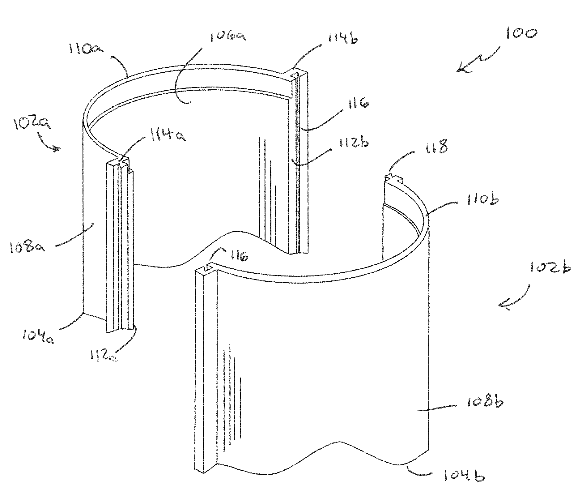
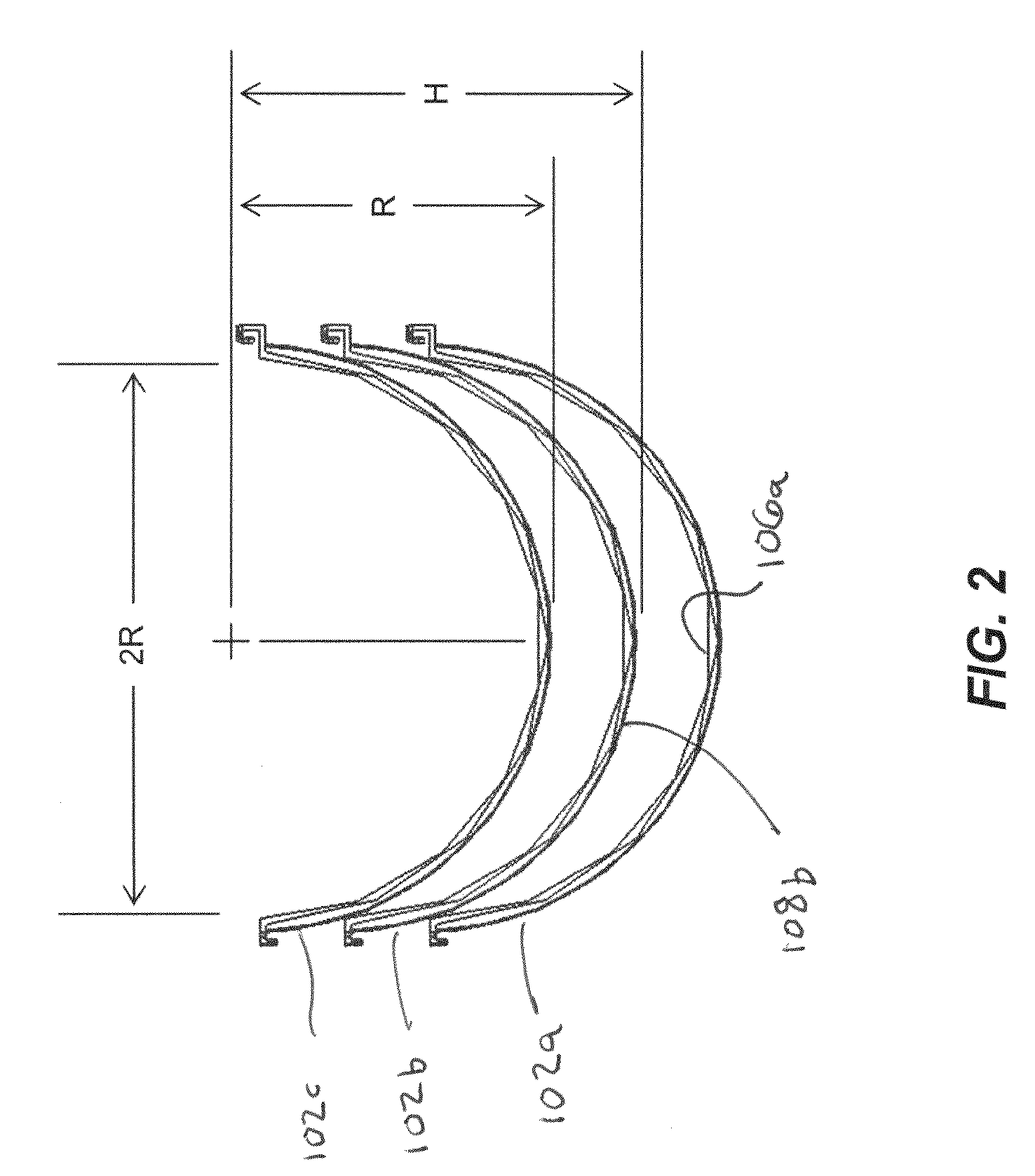
[0060]A hollow column forming structure kit includes multiple elongated wall sections configured for interlocking engagement with each other to form a hollow, open ended structure adapted to accept a settable substance, such as concrete or plaster. The multiple elongated wall sections are stackable and can be stored to shipped to a job site in a condensed or nested configuration. The nested configuration is primarily achieved by avoiding storage or transport with empty hollow space provided by the assembled forms. In some embodiments, the forms can be disassembled after use for transport from the jobsite, storage, and later reuse.

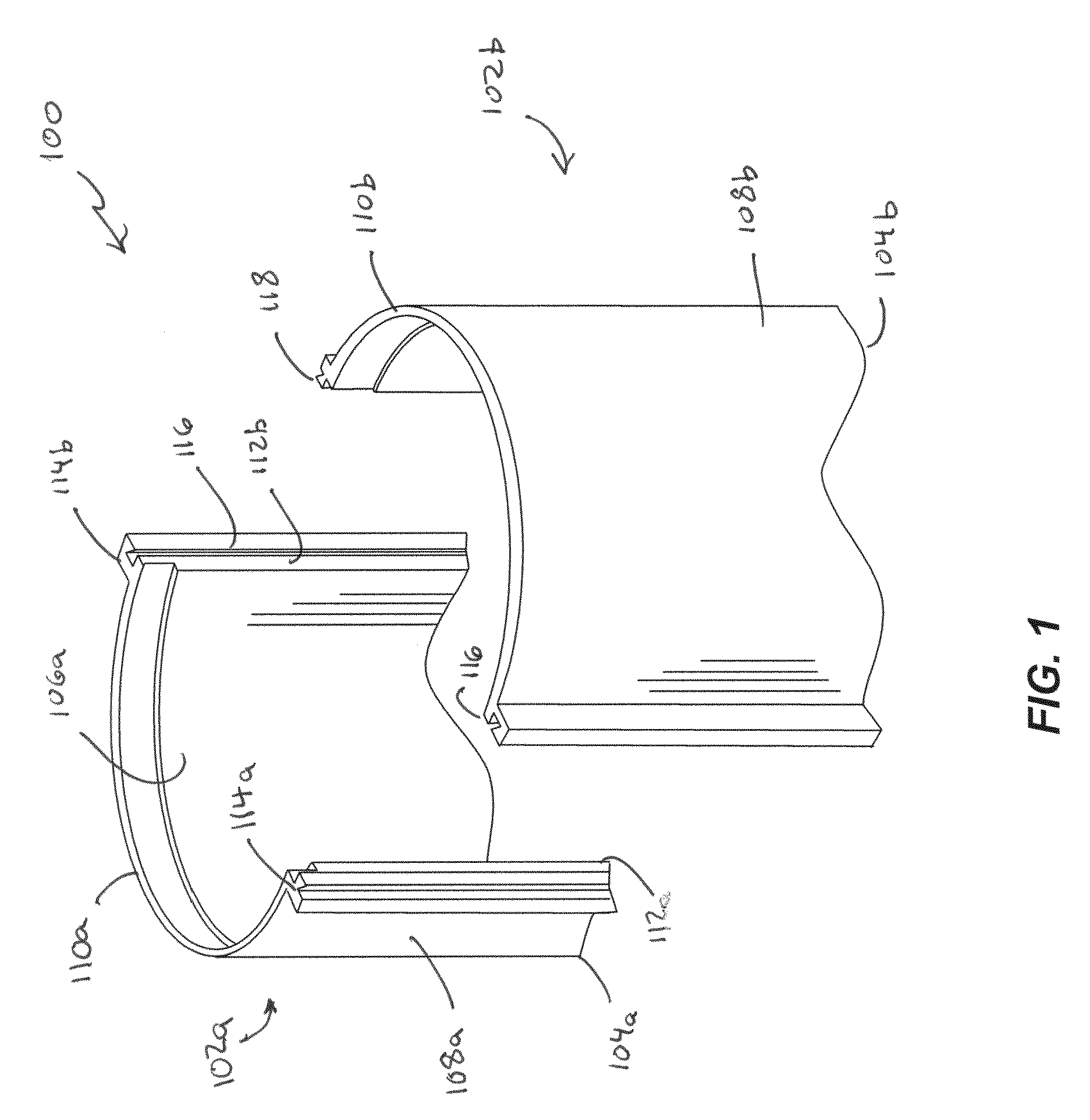
[0061]An exploded top perspective view is shown in FIG. 1 of a top portion of an exemplary embodiment of a concrete column-forming tube kit for constructing a form assembly 100 according to principles of the present invention. The kit for constructing the form assembly 100 includes two lo...


PUM


Abstract

Methods and apparatus providing a column forming assembly formable from multiple column forming sub-assemblies that are stackable providing a compact storage or transport configuration. A column forming structure is formed from multiple elongated wall sections configured for interlocking engagement with each other to form a hollow, open ended structure adapted to accept a settable substance, such as concrete or plaster. The multiple elongated wall sections are stackable and can be stored to shipped to a job site in a condensed or nested configuration. The nested configuration reduces empty or hollow spaces provided by assembled forms. In some embodiments, the forms can be disassembled after use for transport from the jobsite, storage, and later reuse. The column forming assembly can be combined with one or more column-end forms and with thin-walled column forming inserts.

Description

CROSS-REFERENCE TO RELATED PATENT APPLICATIONS[0001]The present application claims priority to U.S. Provisional Patent Application Ser. No. 60 / 846,325, filed on Sep. 21, 2006, which application is incorporated herein by reference in its entirety.FIELD OF THE INVENTION[0002]The present disclosure relates to forms for molding settable materials such as concrete, polymer concrete, or the like and, in particular, to forms for molding concrete column forms and wherein the forms are made of stackable, plastic sections. The present disclosure also relates to form inserts for molding shaped concrete columns and forms for molding concrete footings or capitals for structural pillars.BACKGROUND OF THE INVENTION[0003]In order to construct concrete columns, piers and footings, it is generally necessary to utilize a concrete form. The form act as a mold for pouring concrete to provide a desired size and shape. Among available forms are spirally-wrapped fiber forms, steel sectional forms and fiber...

Claims


Application Information

Patent Timeline
Patent Type & Authority Applications(United States)
IPC IPC(8): E04C3/34
CPCE04C3/34E04G13/021E04G13/02E04G13/028
Inventor WELLS, DONALDWELLS, KAREN
Owner SOUNDFOOTINGS
Learn More