Process for producing slush fluid and apparatus therefor

a technology of slush liquid and process, which is applied in the direction of liquefaction, container filling under pressure, lighting and heating apparatus, etc., can solve the problems of deteriorating transfer efficiency, complicated mechanism, and difficult planning of the gap between the blade of the auger and the cooling surface, and achieves high degree of reliability, simple configuration, and high efficiency

Inactive Publication Date: 2008-03-27
MAYEKAWA MFG CO LTD
View PDF6 Cites 5 Cited by
  • Summary
  • Abstract
  • Description
  • Claims
  • Application Information

AI Technical Summary

Problems solved by technology

However, in the above-mentioned process, a helium refrigerator is required as an additional equipment, and accordingly, there has been caused such a problem that planning of a gap between a blade of the auger and the cooling surface is difficult, and further, the mechanism thereof is complicated.
However, there has been the following problems in the case of application of the above-mentioned slush hydrogen in a cooling system:
However, it has a large absolute value of the pressure loss at a high flow rate so that its transfer efficiency deteriorates; and
Further, as to a long distance cooling for a superconductive power transmission cable or the like, there have been caused the following problems, in addition to the above-mentioned problems:
However, in the process of producing slush nitrogen with the use of the above-mentioned vacuum-evacuation, the solid parts created on the liquid surface by the vacuum evacuation are diffused in the liquid by agitating blades, and accordingly, the particle sizes cannot be uniformly set, some of them having larger particle sizes.

Method used


Image

  • Process for producing slush fluid and apparatus therefor
  • Process for producing slush fluid and apparatus therefor
  • Process for producing slush fluid and apparatus therefor

Examples


embodiment 1

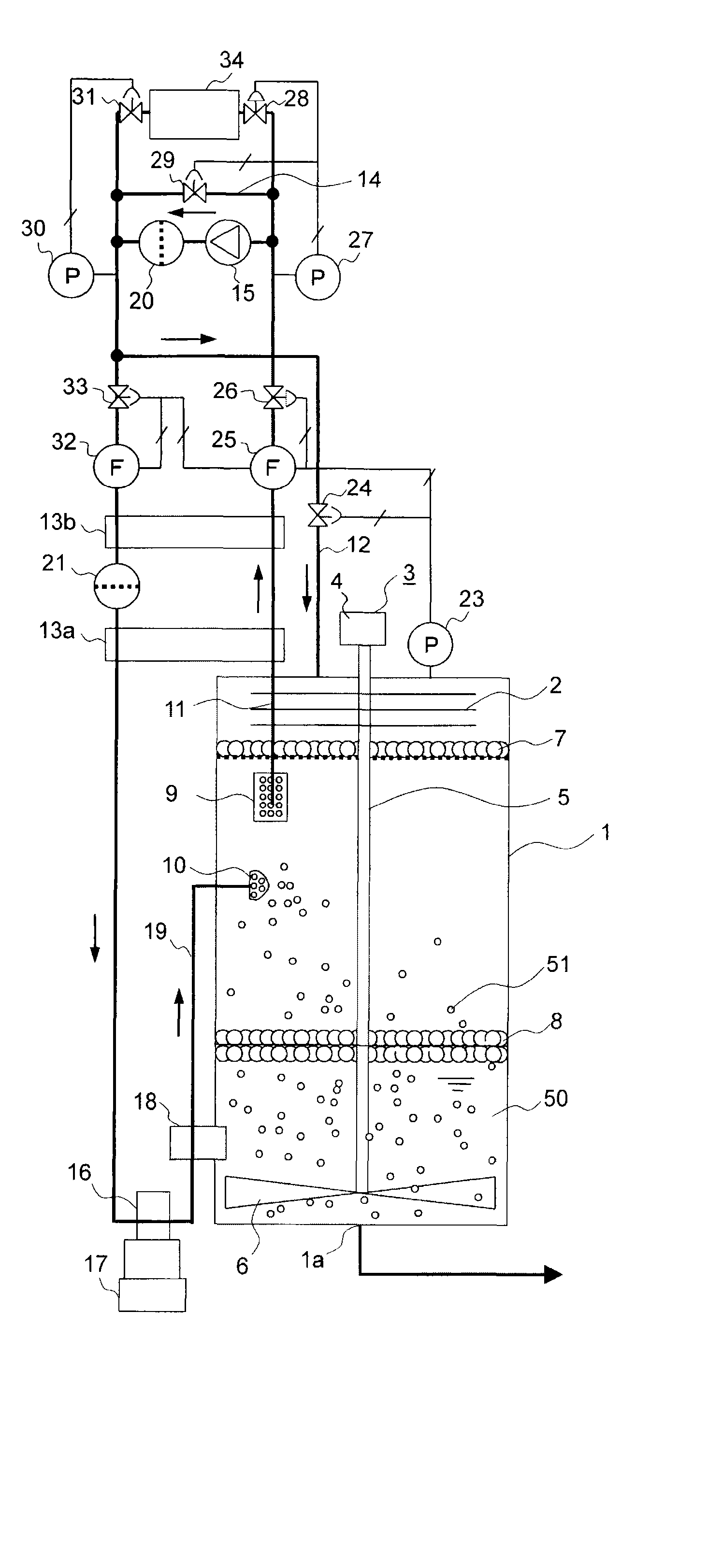
[0063] As shown in FIG. 1, a slush fluid producing apparatus in this embodiment is composed of a slush nitrogen production system including a vacuum heat-insulation type slush nitrogen production tank 1, a nitrogen circulation system for liquefying nitrogen gas vacuum-evacuated from the production tank 1 then returning back into the production tank 1.

[0064] In the above-mentioned slush nitrogen production system, solid nitrogen 51 is created from liquid nitrogen 50 in the production tank 1, and the liquid nitrogen 50 is mixed with a liquid initially charged in the production tank 1 so as to produce slush nitrogen.

[0065] In a specific form of the above-mentioned production tank 1, a plurality of baffle discs 2 are stacked in layers and fixed, in the top part of the production tank 1, and an agitator 3 is inserted in the production tank 1 along the center axis of the tank. The agitator 3 is composed of agitating blades 6 provided in the lower end part of a shaft 4 which is coupled t...

embodiment 2

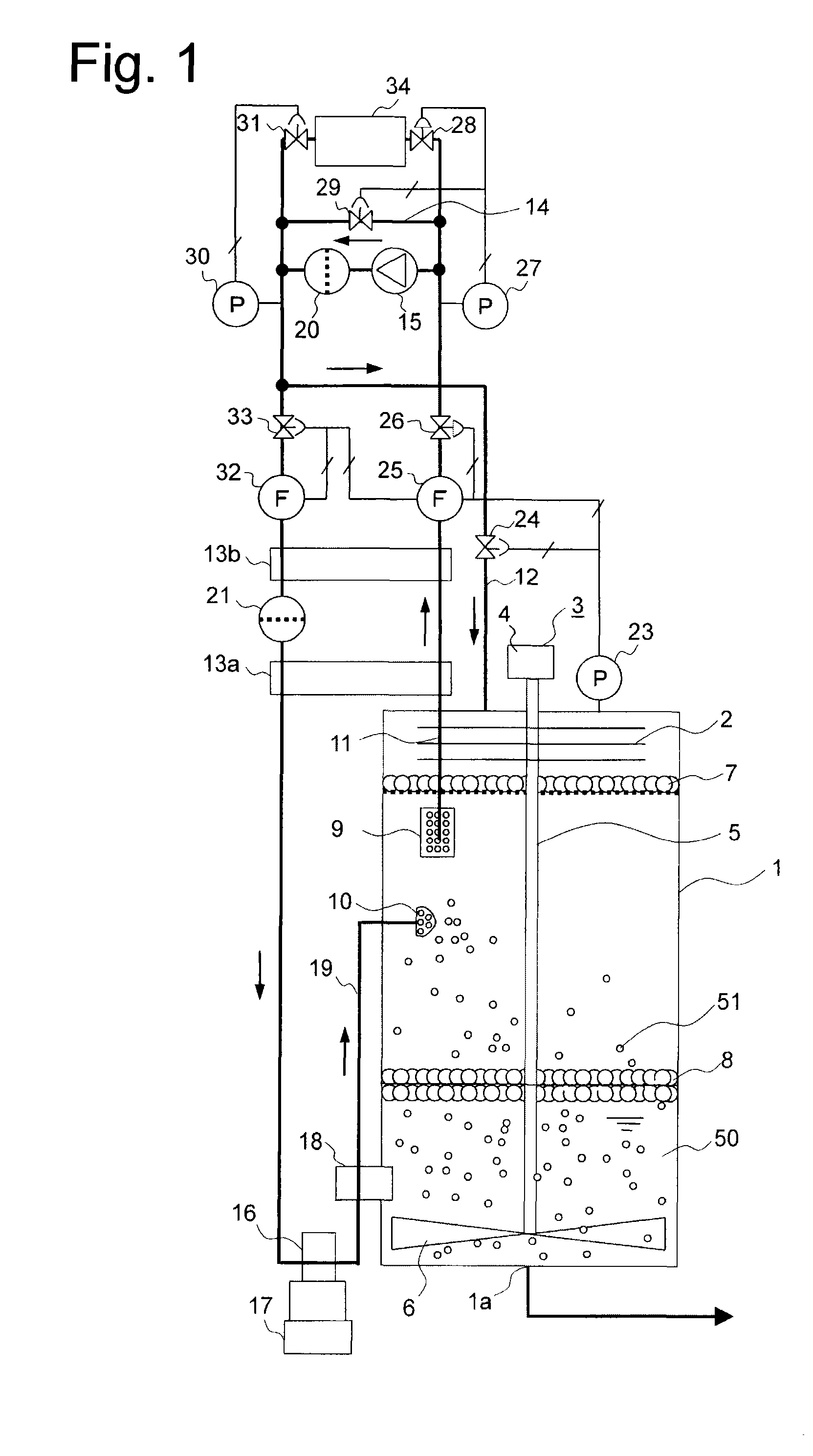
[0081]FIG. 2 shows a production tank 1 in the embodiment 2, which has a configuration different from that shown in FIG. 1. This embodiment 2 is arranged to carry out the gas-liquid separation during the pressurization in the production tank 1 shown in the embodiment 1, in a more surely manner.

[0082] The embodiment 2 has a dual structure composed of a slush nitrogen producing tank 1 in the form of a vacuum adiabatic tank, and an inner container 40 for gas-liquid separation, provided in the production tank 1. The inner container 40 is of a vacuum adiabatic type, and is provided in a floating condition in the liquid nitrogen 50 reserved in the production tank 1 so as to be vertically movable. Accordingly, no liquid is normally present in the inner container 40. The inner container 40 is separated from the production tank 1 so as to be freely movable by its buoyancy, and the inside and the outside of the container are sealed against each other in the ordinary temperature part in the to...

embodiment 3

[0087]FIG. 3 shows a production tank 1 in an embodiment 3, which has a configuration different from that in the embodiment 1. In this embodiment 3, explanation will be made of a configuration which can eliminate such a risk, inherent to the production tank 1 explained in the embodiment 2, that should the solid nitrogen 51 alone be reserved in the inner container 40, the solid nitrogen particles would be stuck to one another, depending upon a certain operating condition.

[0088] The embodiment 3 has a dual structure composed of a slush nitrogen production tank 1 in the form of a vacuum adiabatic container, and an inner container 44 for gas-liquid separation, which is provided in the production container 1. The inner container 44 is of a vacuum adiabatic type, and is separated from the production tank 1, and is provided so as to be vertically movable. An ordinary temperature part defined in the top portion of the inner container 44 is sealed against the inside and outside thereof by se...


PUM


Abstract

An apparatus for producing a slush fluid wherein a liquid and solid particles are mixed together, comprising product tank (1) for storing the slush fluid (50) in its saturated condition; liquid nitrogen supply nozzle (10) provided at an upper part of the product tank (1); and compressor (15) for evacuating the interior of the product tank, which apparatus is adapted to spray a liquid in microparticulate form through the liquid nitrogen supply nozzle (10) into the product tank evacuated by the compressor (15) and to solidify the liquid particles by evaporative latent heat, thereby forming solid nitrogen (51). Preferably, the apparatus has a circulatory system for circulating the gas discharged from the product tank (1) by the compressor (15) to the liquid nitrogen supply nozzle (10), which circulatory system includes heat exchangers (13a,13b) for heating the discharged gas to ordinary temperature by heat exchange; the compressor (15) for compressing the heated gas to thereby produce high-pressure ordinary-temperature gas; the heat exchangers (13a,13b) for cooling the high-pressure ordinary-temperature gas to thereby produce high-pressure low-temperature gas; and auxiliary chilling refrigerator (17) and heat exchanger (16) for chilling the high-pressure low-temperature gas to thereby condense the same.

Description

CROSS REFERENCE TO RELATED APPLICATIONS [0001] This application is a continuation of PCT International Application PCT / JP2005 / 0077944 (published as WO 2006 / 114887) having an international filing date of Apr. 25, 2005. The disclosures of the PCT application is incorporated herein by reference.TECHNICAL FIELD [0002] The present invention relates to a process for producing a slush fluid in which fine solid particles are intermingled in a liquid and an apparatus therefor. DESCRIPTION OF THE RELATED ART [0003] Heretofore, a slush fluid in which fine solid particles are intermingled in a liquid at a cryogenic temperature has been widely used in several technical fields. The slush fluid has such a feature that the density thereof is greater than that of the liquid alone by a value corresponding to the solid particles, and the heat value thereof is higher than that of the liquid by a value corresponding to the latent heat thereof. Further, since a cooled state thereof can be held in a heat ...

Claims


Application Information

Patent Timeline
Patent Type & Authority Applications(United States)
IPC IPC(8): F25J1/02
CPCB01J19/06C01B21/00F25C2301/002F25J1/0015F25J1/004F25J2290/62F25J1/0276F25J2205/20F25J2270/90F25J2280/02F25J1/0208
Inventor IKEUCHI, MASAMITSUMACHIDA, AKITOMATSUO, KOUICHI
Owner MAYEKAWA MFG CO LTD
Why Eureka
Try Eureka