
Machine guard

Active Publication Date: 2008-03-27
THE BOEING CO
View PDF11 Cites 58 Cited by
  • Summary
  • Abstract
  • Description
  • Claims
  • Application Information

AI Technical Summary

Benefits of technology

[0010]The machine guard of the present invention is advantageous in that it is particularly simple in construction and easy to fabricate, but yet provides effective protection of an operator from contact with a rotating drive assembly. The machine guard can be easily retrofitted to existing machine tools such as power-feed, portable drills used extensively throughout industry.

Problems solved by technology

In the case of motor driven, power-feed drills and reamers, the spinning drill / reamer, chuck and spindle pose a safety hazard for the operator.

Method used


Image

  • Machine guard
  • Machine guard
  • Machine guard

Examples


Embodiment Construction

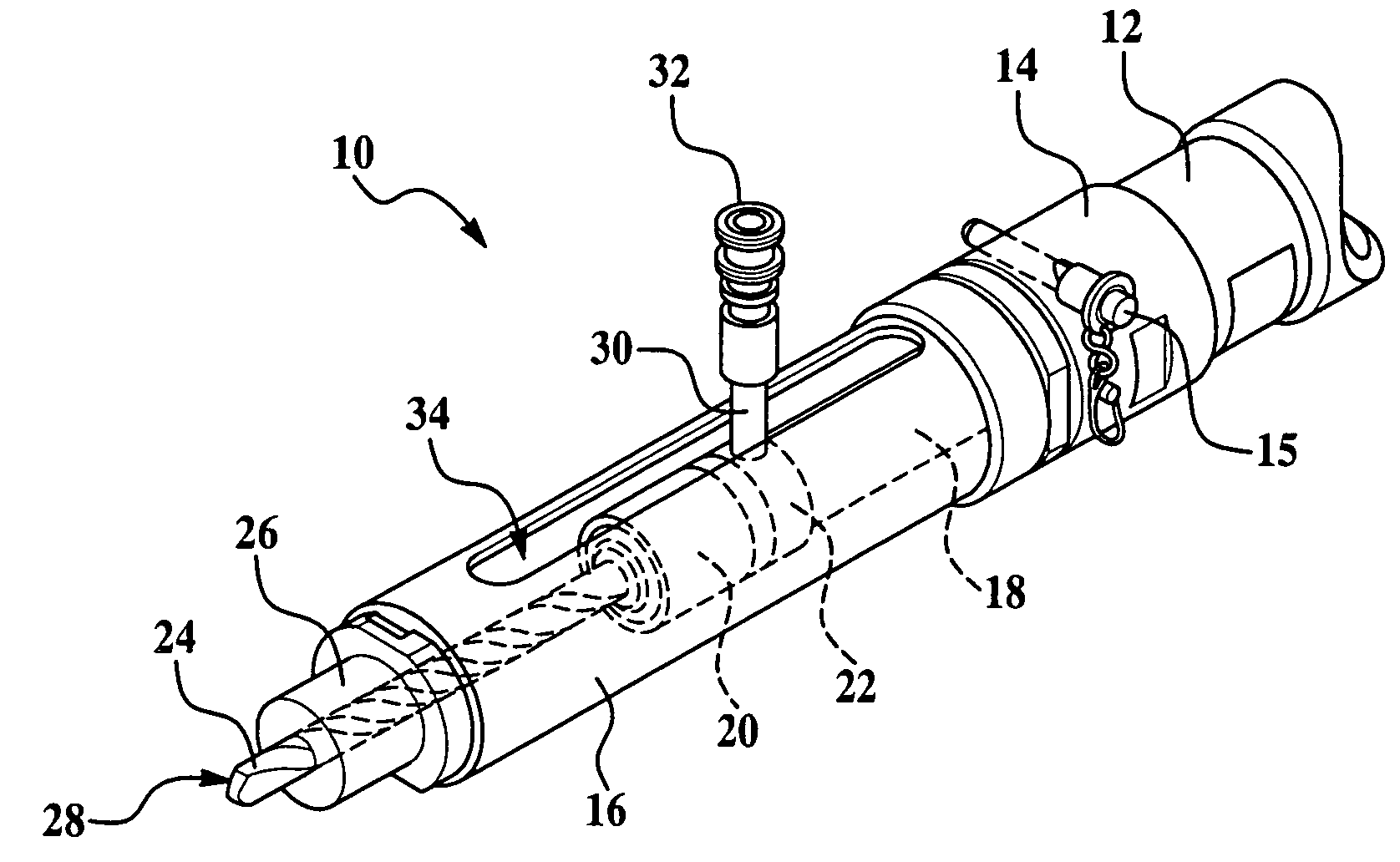
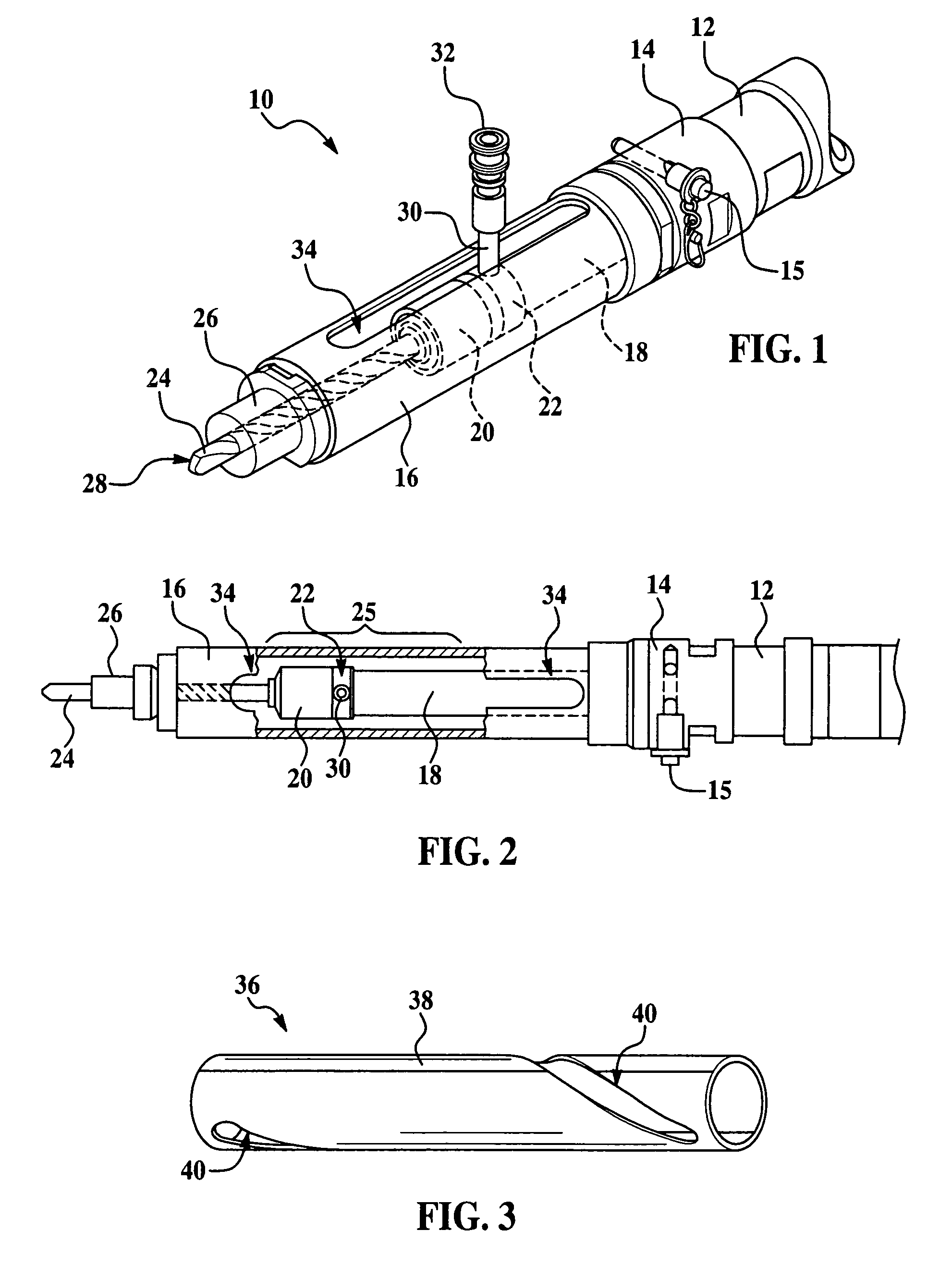
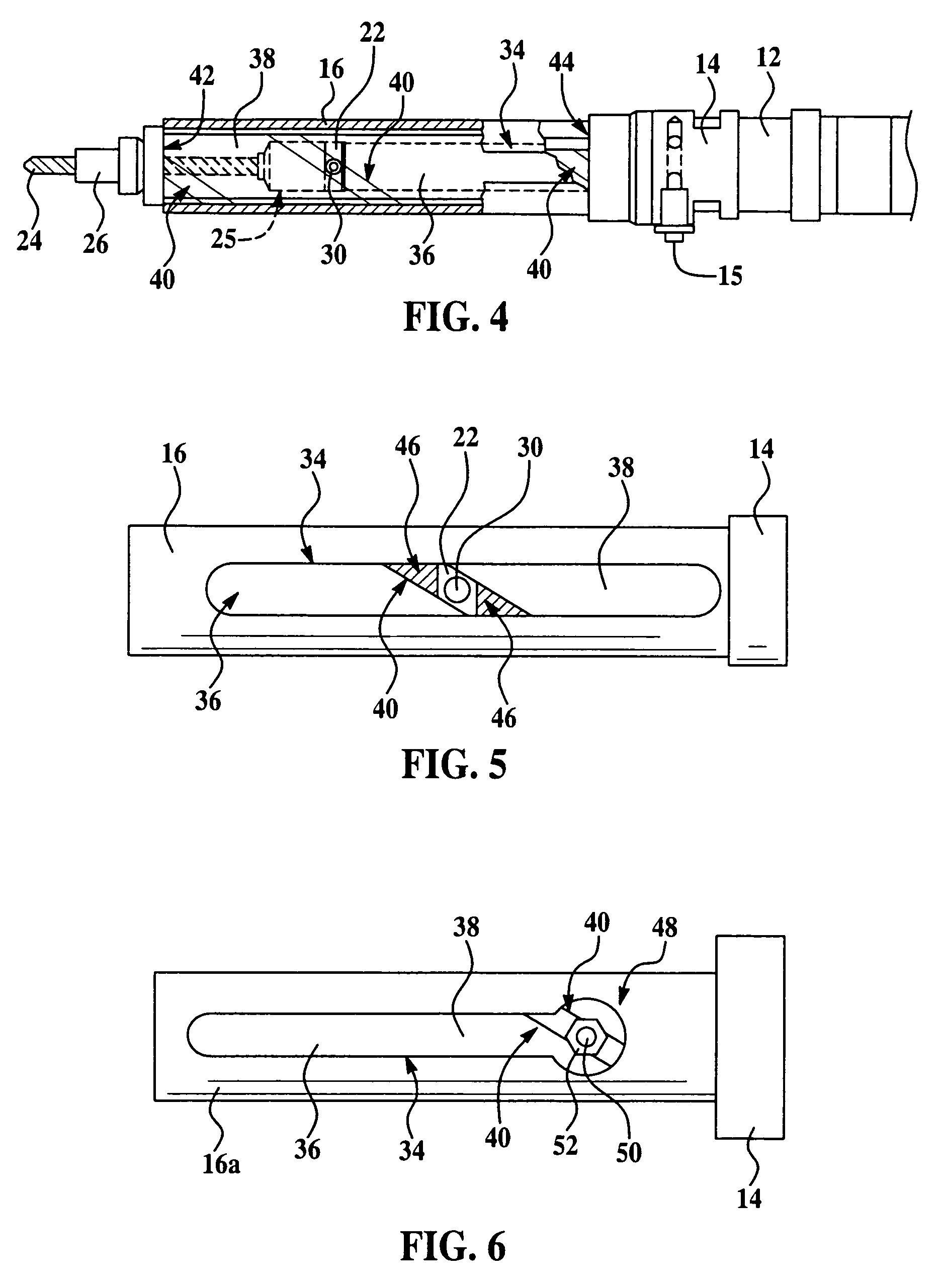
[0021]Referring first to FIGS. 1 and 2, the present invention relates to a machine tool, which in the illustrated example, comprises a power-feed, portable drill having a nose assembly 10 which is connected to an electric motor (not shown) and power feed mechanism (not shown) that linearly displaces the nose assembly 10 during a feed stroke between a retracted position and a displaced position in which a drill tool 24 or similar tool such as a reamer (not shown) performs a machining operation on a workpiece (not shown). Although a power-feed drill has been selected to illustrate use of the machine guard of the present invention, it is to be understood that the inventive machine guard could be used with other types of machines and machine tools that include characteristics of the illustrated drill, including so-called offset powerfeed drills.

[0022]The nose assembly 10 includes the lower end of an electric motor housing 12 to which there is releaseably connected a quick change nosepie...


PUM

PropertyMeasurementUnit
Lengthaaaaaaaaaa
Widthaaaaaaaaaa
Displacementaaaaaaaaaa

Abstract

A guard for a power-feed drill having a fluid inducer protects an operator from coming in contact with a rotating drive assembly. The drive assembly is enclosed by a cylindrical housing having a slotted opening through which a fluid inducer connection extends. The guard comprises a rotatable tube concentrically disposed within the housing and sleeved over the drive assembly so as to cover the opening presented by the slot. The fluid inducer connection passes through a helical groove in the tube.

Description

BACKGROUND OF THE INVENTION[0001]1. Field of the Invention[0002]This invention generally relates to protective guards and safety shields for machine tools, and deals more particularly with a guard for a portable power-feed drill that shields the operator from the rotating spindle assembly and drill tool.[0003]2. Description of the Related Art[0004]A wide array of guards and safety shields have been devised to protect operators from moving parts of machine tools. In the case of motor driven, power-feed drills and reamers, the spinning drill / reamer, chuck and spindle pose a safety hazard for the operator. One type of portable power-feed drill widely used throughout industry employs a fluid inducer to feed cooling fluids or air down through the center of the drill tool to an opening in the end of the tool so that the fluid / air is fed directly to the cutting site. The fluid is fed to the rotating drill tool using a special fluid inducer, which comprises a fluid coupling connected with a...

Claims


Application Information

Patent Timeline
IPC IPC(8): F16P1/00
CPCF16P1/02Y10S408/71Y10T408/44Y10T74/219Y10T409/304032Y10T408/45Y10T74/2191Y10T408/98Y10T409/30392
Inventor CLARK, E-CHARLESSCHEMPP, ROBERT S.
Owner THE BOEING CO
Learn More