Writing method of charged particle beam, support apparatus of charged particle beam writing apparatus, writing data generating method and program-recorded readable recording medium

a technology of writing apparatus and charge particle beam, which is applied in the field of writing or “ drawing” method of charged particle beam, writing data generating method and program-readable recording medium, to achieve the effect of preventing a pattern dimension fluctuation

Active Publication Date: 2008-03-27
NUFLARE TECH INC
View PDF5 Cites 11 Cited by
  • Summary
  • Abstract
  • Description
  • Claims
  • Application Information

AI Technical Summary

Benefits of technology

[0010]It is an object of the present invention to provide a writing method for preventing a pattern dimension fluctuation at the time of a focal positional deviation error being generated, and to provide a method and an apparatus for calculating writing data to be used in the aimed writing method.

Problems solved by technology

However, the optimal dose irradiated in correcting the proximity effect according to the dose change method stated above is not necessarily in accordance with the isofocal dose.

Method used


Image

  • Writing method of charged particle beam, support apparatus of charged particle beam writing apparatus, writing data generating method and program-recorded readable recording medium
  • Writing method of charged particle beam, support apparatus of charged particle beam writing apparatus, writing data generating method and program-recorded readable recording medium
  • Writing method of charged particle beam, support apparatus of charged particle beam writing apparatus, writing data generating method and program-recorded readable recording medium

Examples


embodiment 1

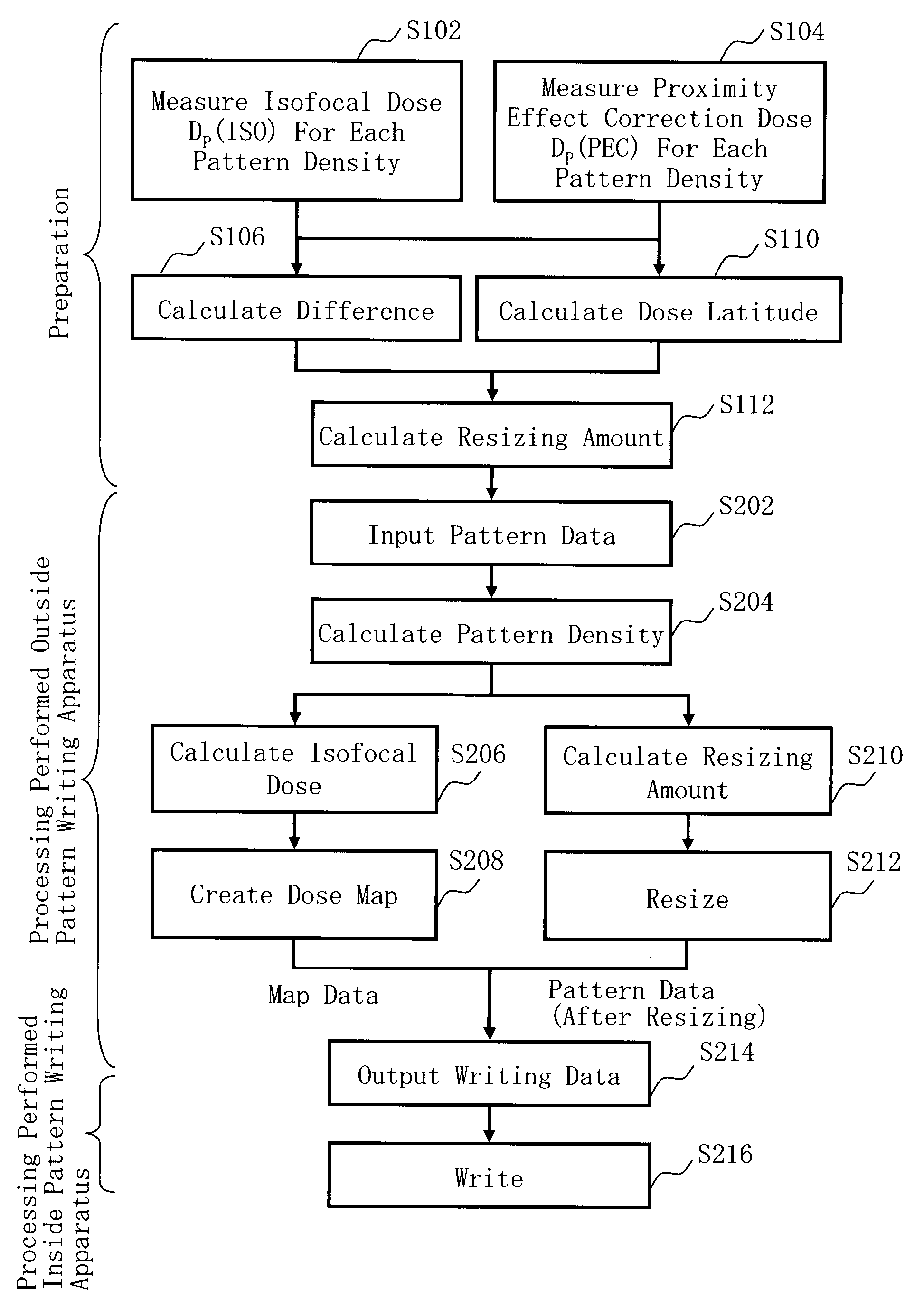
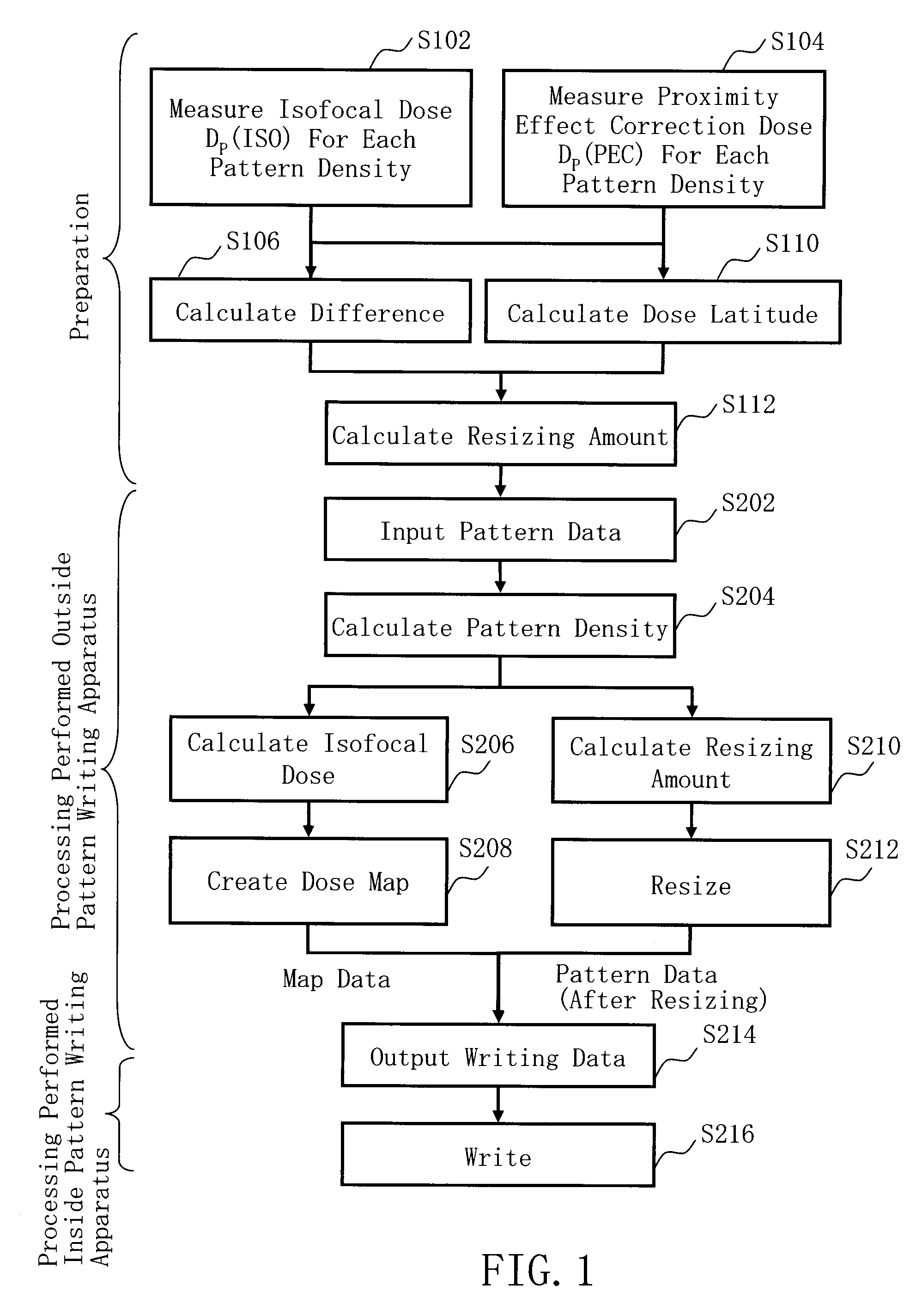
[0046]FIG. 1 is a flowchart showing examples of main steps of an electron beam pattern writing method described in Embodiment 1. In FIG. 1, according to the electron beam pattern writing method serving as an example of a charged particle beam pattern writing method, a series of the following steps is executed as preparatory steps: an isofocal dose Dp (ISO) measurement step (S102) for each pattern density, a proximity effect correction dose Dp (PEC) measurement step (S104) for each pattern density, a difference calculation step (S106), a dose latitude calculation step (S110), and a resizing amount calculation step (S112). By performing these steps, a correlation between a pattern density and an isofocal dose, and a correlation between a pattern density and a resizing amount can be acquired. Next, as processing performed outside the pattern writing apparatus serving as a writing data generating method, a series of the following steps is executed: a pattern data input step (S202), a pa...

embodiment 2

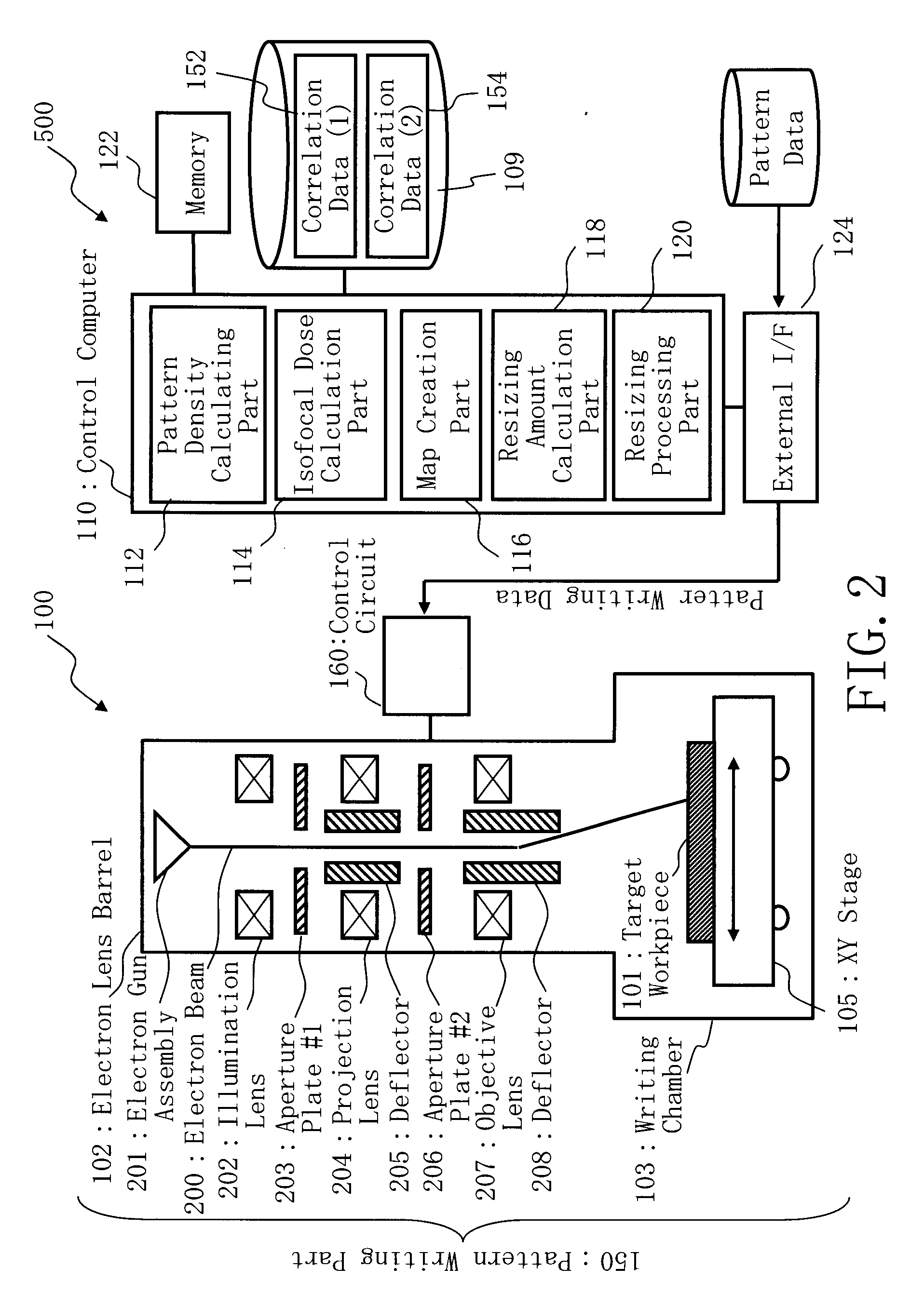
[0076]As mentioned above, according to Embodiment 1, the isofocal dose etc. is measured only in the evaluation patterns 12, 14, and 16 shown in FIG. 3. Based on a result of the measuring, the correlation data (1) 152 and the correlation data (2) 154 are generated. Then, based on these data and a pattern density in a mesh in which the proximity effect is taken into consideration, to be explained in detail later, an isofocal dose for the case of writing design pattern data is calculated. A resizing amount is also calculated similarly. If influence around the evaluation patterns 12, 14, and 16 is taken into account, further highly precise isofocal dose etc. can be measured. For this reason, in Embodiment 2, the structure in the case of taking the influence around the evaluation pattern into consideration will be explained. The structures of the support apparatus 500 and the pattern writing apparatus 100 in Embodiment 2 are the same as those of Embodiment 1. Moreover, the steps up to th...


PUM


Abstract

A charged particle beam writing method includes inputting design pattern data, virtually dividing a writing area to be written with the design pattern data into a plurality of small areas in a mesh-like manner, calculating a pattern density in each of the plurality of small areas based on the design pattern data, calculating a resizing amount for each pattern density in a case of irradiating a charged particle beam at an isofocal dose, resizing a dimension of the design pattern data in each of the plurality of small areas, based on the resizing amount in each of the plurality of small areas, and writing a resized design pattern on a target workpiece with the isofocal dose corresponding to the pattern density which was calculated before the resizing in each of the plurality of small areas.

Description

CROSS-RELATION TO RELATED APPLICATION[0001]This application is based upon and claims the benefit of priority from the prior Japanese Patent Application No. 2006-062047 filed on Mar. 8, 2006 in Japan, the entire contents of which are incorporated herein by reference.BACKGROUND OF THE INVENTION[0002]1. Field of the Invention[0003]The present invention relates to a writing or “drawing” method of a charged particle beam, a generating or “creating” method of writing data, and a computer-readable recording medium with a program recorded thereon. For example, it is related with an electron beam writing method of irradiating electron beams onto a target workpiece while variably-shaping the electron beams, or a generating method of writing data to be input into an electron beam pattern writing apparatus. Alternatively, it is related with a program for embodying these methods.[0004]2. Description of Related Art[0005]Microlithography technology which forwards miniaturization of semiconductor d...

Claims


Application Information

Patent Timeline
Patent Type & Authority Applications(United States)
IPC IPC(8): A61N5/00H01L21/027
CPCB82Y10/00H01J37/3174H01J37/3026B82Y40/00Y10S430/143
Inventor KAMIKUBO, TAKASHI
Owner NUFLARE TECH INC
Why Eureka
Try Eureka