Imprint apparatus and imprint method

a technology of imprinting apparatus and imprinting method, which is applied in the direction of photomechanical apparatus, instruments, nanoinformatics, etc., can solve the problems of difficult alignment of mold and workpiece, long alignment time, and inability to achieve the mark provided on the surface of workpieces

Inactive Publication Date: 2008-03-27
CANON KK
View PDF4 Cites 20 Cited by
  • Summary
  • Abstract
  • Description
  • Claims
  • Application Information

AI Technical Summary

Benefits of technology

[0030]According to the present invention, it is possible to provide an imprint apparatus capable of performing high-precision alignment when a distance between the mold and the workpiece changes and an alignment method for imprint apparatus.

Problems solved by technology

In the case of the first wavelength, although focus is achieved on the mark provided on the surface of the mold, focus is not achieved on the mark provided on the surface of the workpiece.
Therefore, when the mold and the workpiece are continuously changed in a direction perpendicular to a working surface, it is difficult to align the mold and the workpiece.
However, in the case of a nanoimprint apparatus, the distance between a mold and a workpiece which are opposed to each other continuously changes, so it is required to align the mold and the workpiece with respect to an arbitrary gap.
When the position shift is large, the alignment takes a long time.

Method used


Image

  • Imprint apparatus and imprint method
  • Imprint apparatus and imprint method
  • Imprint apparatus and imprint method

Examples


embodiment 1

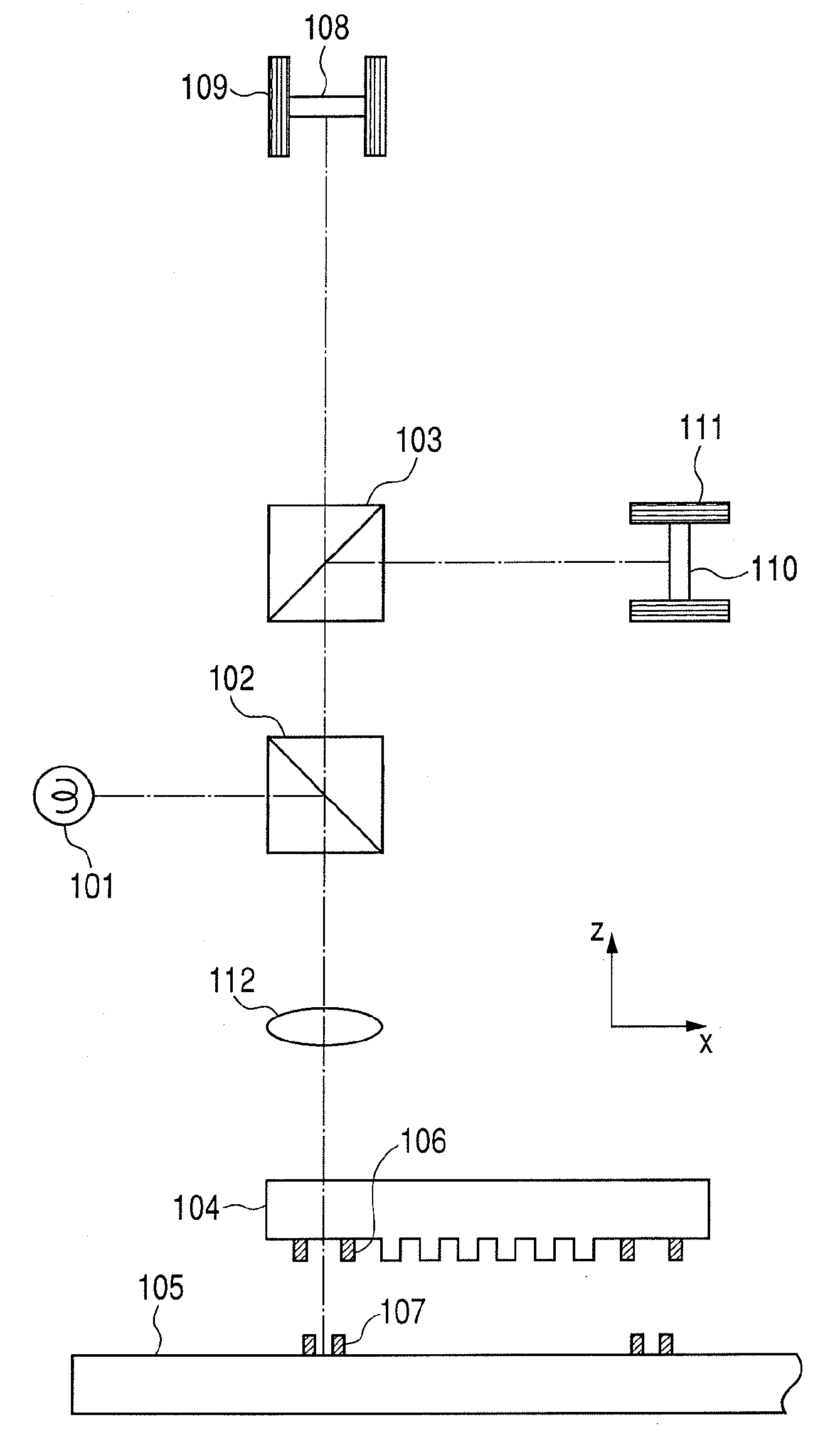
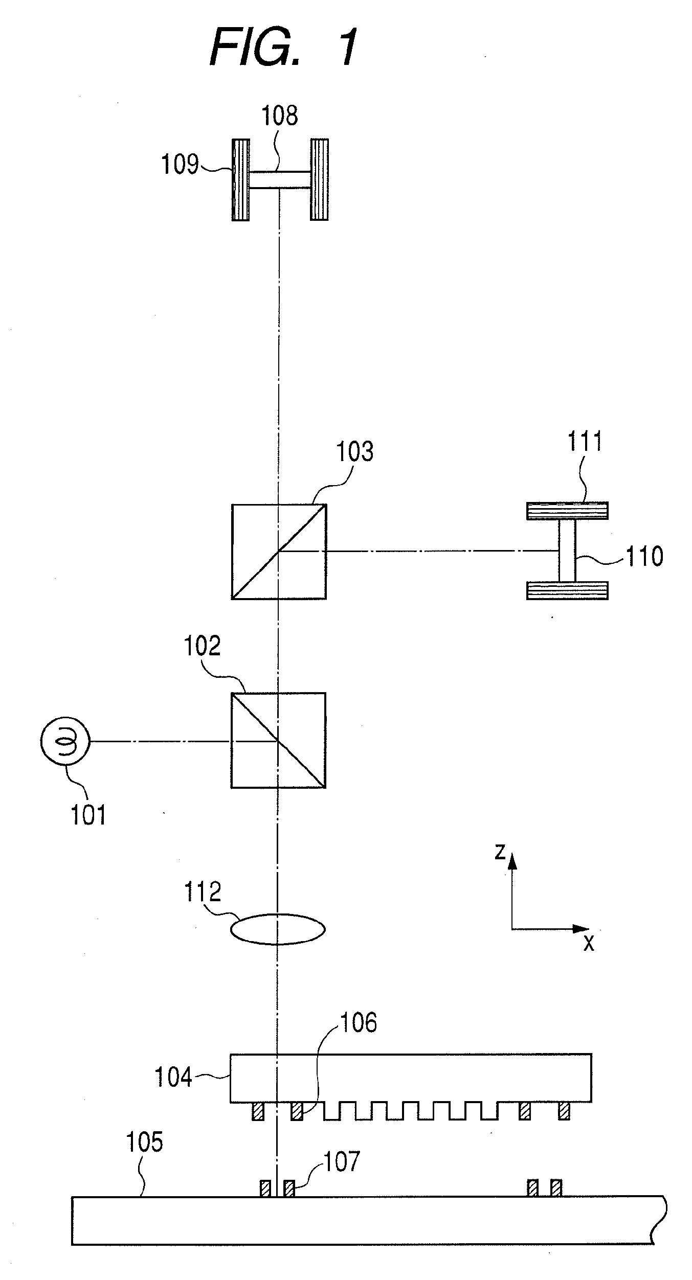
[0051]In Embodiment 1, an optical system used for an imprint apparatus to which the present invention is applied will be described. FIG. 1 is an explanatory view illustrating the optical system of Embodiment 1.

[0052]In FIG. 1, the optical system includes a light source 101, a first beam splitter 102, and a second beam splitter 103.

[0053]A mold 104 has an imprint pattern. A workpiece 105 is opposed to the mold 104.

[0054]In this specification, the mold 104 may be referred to as a first object and the workpiece 105 may be referred to as a second object. The workpiece 105 may be also referred to as a member to be worked because the imprint pattern of the mold is transferred thereto.

[0055]A Mold mark 106 is arranged to the mold 104. A Workpiece mark 107 is arranged to the workpiece 105. The mold mark 106 and the workpiece mark 107 may be provided on the surfaces of the mold 104 and the workpiece 105 or embedded therein.

[0056]A first drive mechanism 109 for moving a first image pick-up de...

embodiment 2

[0115]In Embodiment 2, an optical system capable of adjusting a magnification used for the imprint apparatus will be described.

[0116]FIG. 5 is an explanatory diagram illustrating the optical system in this embodiment.

[0117]In FIG. 5, the same constituent elements as those of Embodiment 1 as illustrated in FIG. 1 are expressed by the same reference numerals and thus the description of common portions are omitted.

[0118]As illustrated in FIG. 5, reference numeral 501 denotes a first magnification-variable optical component and reference numeral 502 denotes a second magnification-variable optical component.

[0119]The optical system in this embodiment includes the first magnification-variable optical component 501 for adjusting imaging magnification for the first image pick-up device 108 and the second magnification-variable optical component 502 for adjusting imaging magnification for the second image pick-up device 110.

[0120]To be specific, the first magnification-variable optical compo...

embodiment 3

[0122]In Embodiment 3, an optical system including a mold reference mark and a workpiece reference mark, which is used for the imprint apparatus, will be described.

[0123]FIG. 6 is an explanatory diagram illustrating the optical system in this embodiment.

[0124]In FIG. 6, the same constituent elements as those of Embodiments 1 and 2 as illustrated in FIGS. 1 and 5 are expressed by the same reference numerals and thus the description of common portions are omitted.

[0125]In FIG. 6, the optical system includes a mold reference mark member (third object) 601 in which a reference mark is provided, a mold reference mark member drive mechanism (third drive mechanism) 602, a workpiece reference mark member (fourth object) 603 in which a reference mark is provided, and a workpiece reference mark member drive mechanism (fourth drive mechanism) 604.

[0126]In Embodiment 3, each of the first image pick-up device and the second image pickup device is shifted from the optical axis, so the mold refere...


PUM


Abstract

An imprint apparatus, comprising a first holder for holding a mold having an imprint pattern; a second holder for holding a workpiece to which the imprint pattern is transferred; a first illumination system for irradiating a mark for determining a position of the mold and a mark for determining a position of the workpiece with light; a first and second optical systems for imaging the marks for the mold and workpiece at a first and second observation points respectively; an imaging optical system; a first and second image pick-up devices for observing the marks for the mold and workpiece respectively; and at least one of a first drive mechanism for moving the first image pick-up device while following movement of the first observation point and a second drive mechanism for moving the second image pick-up device while following movement of the second observation point.

Description

BACKGROUND OF THE INVENTION[0001]1. Field of the Invention[0002]The present invention relates to an imprint apparatus and an imprint method which are used for transferring a mold shape to a workpiece.[0003]2. Description of the Related Art[0004]In recent years, as described in “Stephan Y. Chou et. al., Appl. Phys. Lett, 67, 3114, 1995”, a fine processing technique for pressurizing and transferring a fine structure provided on a mold to a work such as a semiconductor, a glass, a resin, or a metal has been developed and attracted attention.[0005]This technique is called nanoimprint or nanoembossing because of a resolution of the order of several nanometers. According to this technique, a three-dimensional structure can be collectively processed at a wafer level at once. Therefore, the technique is expected to be applied to a wide variety of fields in addition to manufacturing the semiconductor.[0006]For example, the technique is expected to be applied to manufacturing techniques for a...

Claims


Application Information

Patent Timeline
Patent Type & Authority Applications(United States)
IPC IPC(8): G06K9/00
CPCB82Y10/00B82Y40/00G03F7/0002G06K9/325G03F9/7042G03F9/7088G03F9/7003G06V20/62
Inventor SUEHIRA, NOBUHITOSEKI, JUNICHIINA, HIDEKISENTOKU, KOICHI
Owner CANON KK
Why Eureka
Try Eureka