Frequency-selective oscillator

a technology of selective oscillator and frequency, which is applied in the direction of oscillator, generating/distributing signals, pulse technique, etc., can solve the problems of affecting the downsizing of the entire device, and achieve the elimination of dc level fluctuation, good output voltage characteristics, and the effect of reducing the downsizing of the devi

Inactive Publication Date: 2008-03-27
NIHON DEMPA KOGYO CO LTD
View PDF1 Cites 4 Cited by
  • Summary
  • Abstract
  • Description
  • Claims
  • Application Information

AI Technical Summary

Benefits of technology

[0015] The present invention has been made in view of the actual conditions, and it is an object thereof to provide a frequency-selective oscillator capable of outputting two frequencies without hindering the downsizing of the device and capable of obtaining good output voltage characteristics.
[0016] The present invention made to solve the above-mentioned conventional problem provides a frequency-selective oscillator comprising: a first crystal resonator oscillating a first frequency; a first oscillation circuit connected to the first crystal resonator; a second crystal resonator oscillating a second frequency; and a second oscillation circuit connected to the second crystal resonator, wherein a common frequency-switching voltage signal is applied to selector terminals of the first oscillation circuit and the second oscillation circuit, a supply voltage is applied to a switching control terminal of the first oscillation, circuit, a switching control terminal of the second oscillation circuit is grounded, and the output of the first oscillation circuit and the output of the second oscillation circuit are connected and output from a common signal line, whereby first and second different frequencies can be output without hindering the downsizing of the oscillator.
[0017] According to the present invention, the above-mentioned frequency-selective oscillator can be such that a first common signal line and a second common signal line are connected through an inductor. In this structure, there is no electric potential difference between the first and second common signal lines, so that the DC level fluctuation can be eliminated and hence the duty cycle can be improved, thereby obtaining good output voltage characteristics.
[0018] Further, according to the present invention, the above-mentioned frequency-selective oscillator can be such that the impedance of the inductor is set to compensate for the impedance of parasitic capacitance generated between the first common signal line and the second common signal line. In this structure, the influence of parasitic capacitance can be reduced to prevent the amplitude of the output signal from being decreased, thereby obtaining good output voltage characteristics.

Problems solved by technology

Therefore, in order to output two different frequencies, two conventional oscillators are needed as separate devices, resulting in a problem of hindering the downsizing of the entire device.

Method used


Image

  • Frequency-selective oscillator
  • Frequency-selective oscillator
  • Frequency-selective oscillator

Examples


first embodiment

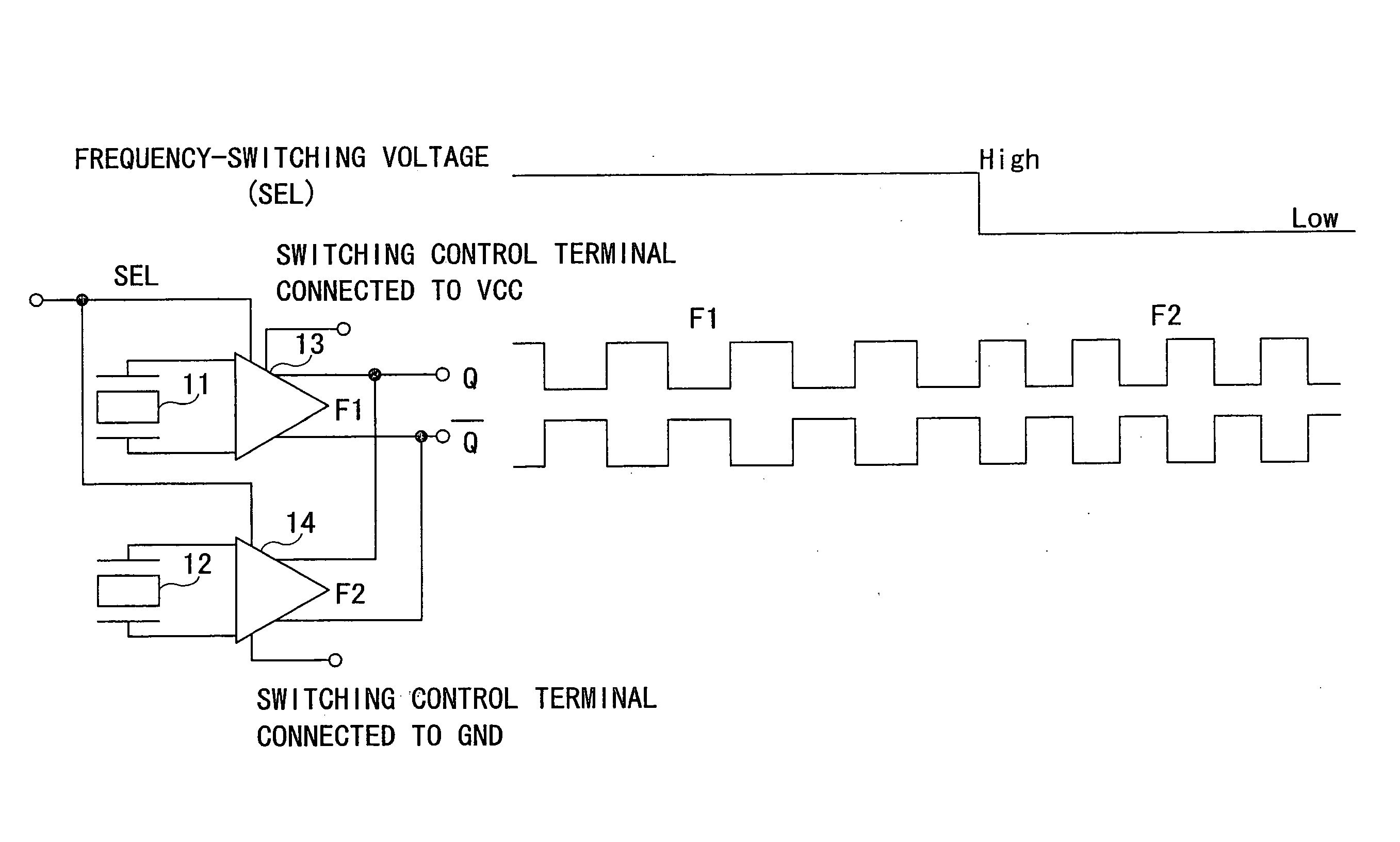
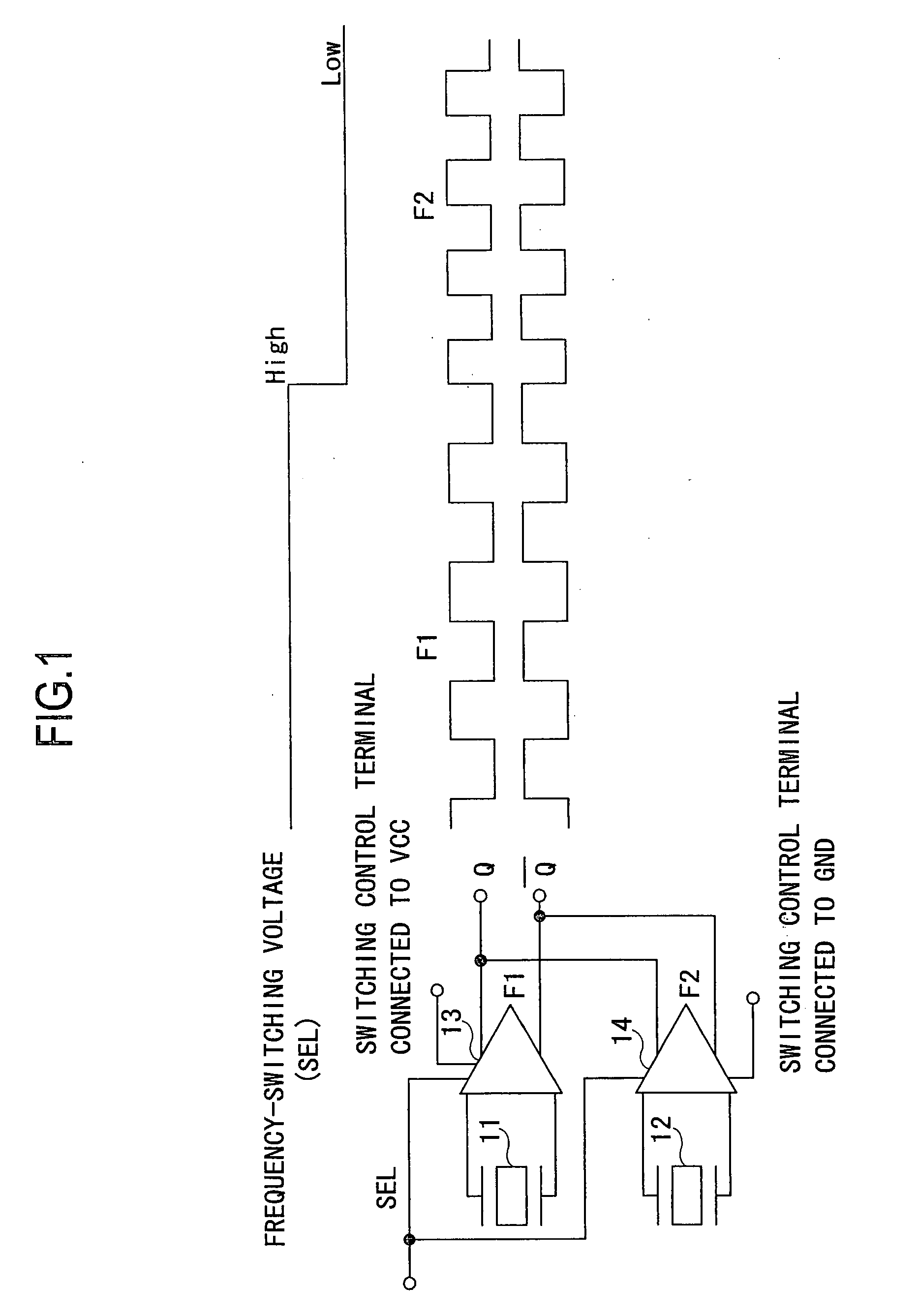
[0048] The frequency-selective oscillator according to the present invention includes the first crystal resonator 11 and the second crystal resonator 12 different in oscillation frequency, and the first oscillation circuit 13 and the second oscillation circuit 14 corresponding to respective crystal resonators. In this structure, the frequency-switching voltage is applied to the selector terminals of the first and second oscillation circuits, the supply voltage Vcc is applied to the switching control terminal of the first oscillation circuit 13, the switching control terminal of the second oscillation circuit 14 is grounded, the Q outputs of the two oscillation circuits are connected to provide the common Q output, and the inverted Q outputs are connected to provide the common inverted Q output. Therefore, when the frequency-switching voltage is High, Q and inverted Q are output with the frequency F1 from the first oscillation circuit 13, while when the frequency-switching voltage is...

second embodiment

[0049] A frequency-selective oscillator according to the present invention will next be described.

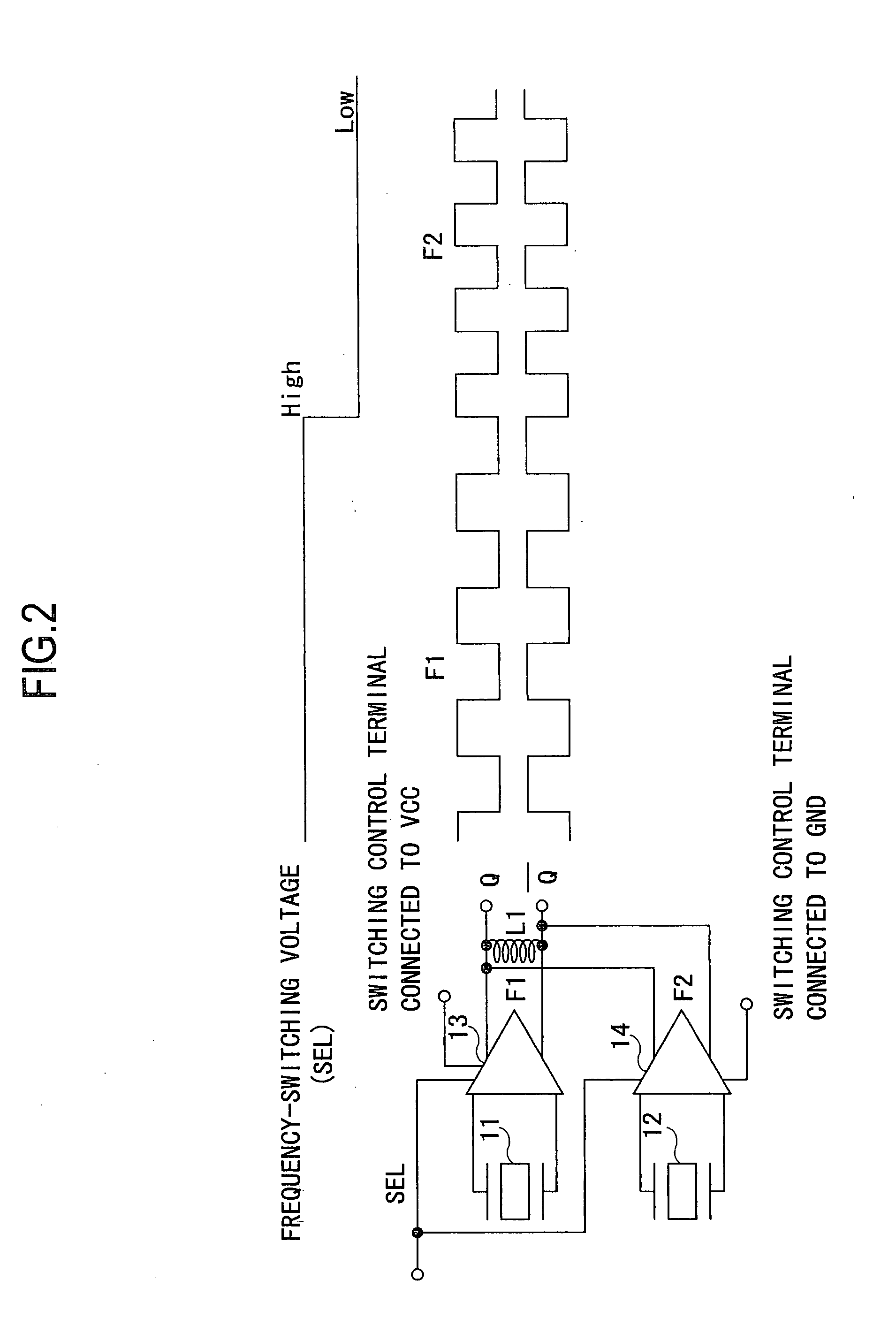
[0050]FIG. 2 is a schematic diagram showing circuitry and operation timing of a frequency-selective oscillator (second circuitry) according to the second embodiment of the present invention.

[0051] As shown in FIG. 2, the second circuitry has such a structure that the Q output and the inverted Q output of the first circuitry shown in FIG. 1 are connected through an inductor L1 for the purpose of improving the output characteristics of the first circuitry. Note that, since the structural components and operation timing of the second circuitry are the same as those of the first circuitry except for the inductor L1, redundant description thereof will be omitted.

[0052] Since the first circuitry shown in FIG. 1 outputs signals alternately from the two oscillation circuits, the output amplitude could be decreased due to the influence of parasitic capacitance of the oscillation stopping oscil...


PUM


Abstract

The object of the present invention is to provide a frequency-selective oscillator capable of outputting two frequencies without hindering the downsizing of the device and capable of obtaining good output voltage characteristics. The frequency-selective oscillator includes a first crystal resonator and a second crystal resonator different in oscillation frequency from each other, and a first oscillation circuit and a second oscillation circuit corresponding to respective crystal resonators, in which a frequency-switching voltage is applied to selector terminals of the first and second oscillation circuits, a supply voltage Vcc is applied to a switching control terminal of the first oscillation circuit, a switching control terminal of the second oscillation circuit is grounded, Q outputs and inverted Q outputs of the oscillation circuits and are respectively connected and output from respective common signal lines. The frequency-selective oscillator can also be such that the common Q output and the common inverted Q output in the above structure are connected through an inductor L1.

Description

BACKGROUND OF THE INVENTION [0001] 1. Field of the Invention [0002] The present invention relates to a frequency-selective oscillator for outputting two difference frequencies, and more particularly to a compact frequency-selective oscillator capable of obtaining a stable output voltage. [0003] 2. Description of the Related Art [0004] Conventional oscillators will be described with reference to FIGS. 10 and 11. FIG. 10 is a schematic diagram showing circuitry and operation timing of a first conventional oscillator, and FIG. 11 is a schematic diagram showing circuitry and operation timing of a second conventional oscillator. [0005] As shown in FIG. 10, the first conventional oscillator is composed of a crystal resonator 1 oscillating a constant frequency, and an oscillation circuit 2 formed as an oscillator IC for tuning and amplifying the frequency from the crystal resonator 1. In this structure, a frequency-switching voltage (SEL) arbitrarily switchable between a high level (High) ...

Claims


Application Information

Patent Timeline
Patent Type & Authority Applications(United States)
IPC IPC(8): H03B5/30
CPCG06F1/08H03K3/0307H03B5/36
Inventor MATSUMOTO, TAKASHI
Owner NIHON DEMPA KOGYO CO LTD
Why Eureka
Try Eureka