Apparatus and method for providing protection for a synchronous electrical generator in a power system

Active Publication Date: 2008-03-27
SCHWEITZER ENGINEERING LABORATORIES
View PDF22 Cites 37 Cited by
  • Summary
  • Abstract
  • Description
  • Claims
  • Application Information

AI Technical Summary

Benefits of technology

[0015]According to another embodiment of the invention, in a protective relay, a method provides protection for a synchronous generator. The method includes selecting at least one of a plurality of generator safe operating boundary data expressions based on a predetermined user programmable input and a generator operating indication. The plurality of generator safe operating boundary data expressions is derived from either an SSSL curve, a plurality of generator safe operating boundaries supplied by a manufacturer of the synchronous generator, or other similar means. The method also includes calculating an active power value sum and a reactive power value sum based on measured three-phase currents and voltages associated with synchronous generator operation. The method further includes comparing the active power value sum and the reactive power value sum to the at least one of the plurality of generator safe operating boundary data expressions, and providing the protection for the synchronous generator based on this comparison.
[0016]An apparatus provides protection for a synchronous generator in a power system. The apparatus comprises a means for deriving a plurality of digitized signals representative of measured three-phase secondary currents and voltages associated with synchronous generator operation, and a microcontroller operatively coupled to the means for deriving the plurality of digitized signals. The microcontroller includes a microprocessor and a memory operatively coupled to the microprocessor. The microcontroller is programmed to, based on a plurality of predetermined user programmable inputs and generator operating indications, select at least one of a plurality of generator safe operating boundary data expressions. The plurality of generator safe operatin

Problems solved by technology

Because there are limits to the amount of current that can flow through the stator and rotor winding, the operating limits reflected in the capability curves are imposed on the amount of Watts and VARs that the synchronous generator can deliver to the power system.
There is also a minimum value of current that must flow in the roto

Method used


Image

  • Apparatus and method for providing protection for a synchronous electrical generator in a power system
  • Apparatus and method for providing protection for a synchronous electrical generator in a power system
  • Apparatus and method for providing protection for a synchronous electrical generator in a power system

Examples


Example

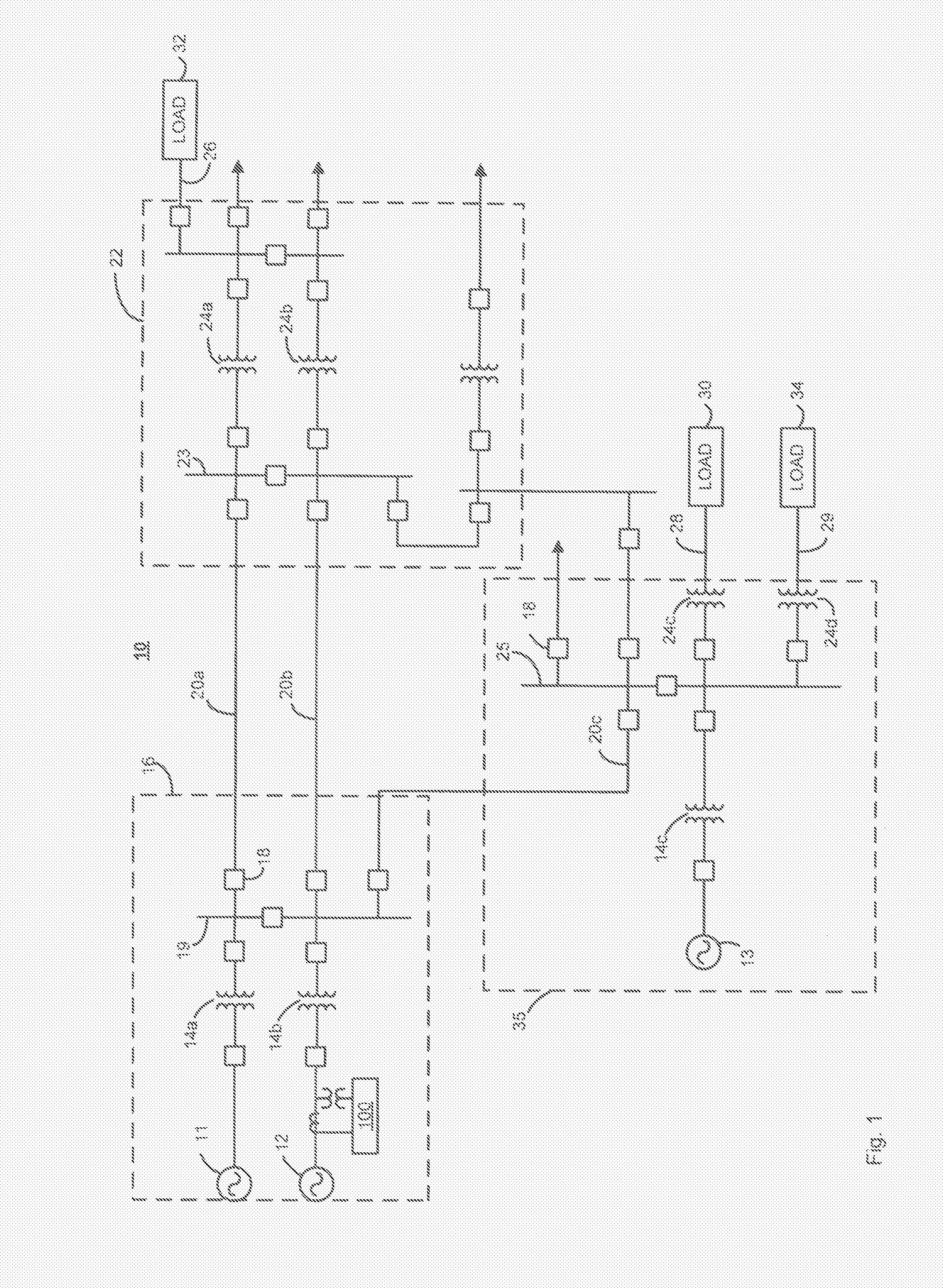
[0035]FIG. 1 is a single line schematic diagram of a power system 10 that may be utilized in a typical wide area system. As illustrated in FIG. 1, the power system 10 includes, among other things, three synchronous generators 11, 12 and 13, configured to generate three-phase voltage sinusoidal waveforms such as 12 kV sinusoidal waveforms, three step-up power transformers 14a, 14b and 14c, configured to increase the generated voltage sinusoidal waveforms to higher voltage sinusoidal waveforms such as 138 kV sinusoidal waveforms and a number of circuit breakers 18. The step-up power transformers 14a, 14b, 14c operate to provide the higher voltage sinusoidal waveforms to a number of long distance transmission lines such as the transmission lines 20a, 20b and 20c. In an embodiment, a first substation 16 may be defined to include the two synchronous generators 11 and 12, the two step-up power transformers 14a and 14b and associated circuit breakers 18, all interconnected via a first bus ...


PUM


Abstract

An apparatus and method provide protection for a synchronous generator in a power system. The method includes deriving a plurality of generator safe operating boundary data expressions from power system data and/or user-defined inputs. The power system data may include a plurality of generator data supplied by a manufacturer of the generator and/or power system parameters such as power system equivalent impedance. Each generator safe operating boundary data expression may relate to a generator capability curve, a steady-state stability limit curve, a minimum excitation limiter curve, an over excitation limiter curve, or an user-defined curve. The method also includes calculating an active power value sum and a reactive power value sum based on generator three-phase currents and voltages, comparing these sums to at least one of the plurality of generator safe operating boundary data expressions, and to provide protection and/or alarming functions for the generator based on this comparison.

Description

CROSS-REFERENCE TO RELATED APPLICATIONS[0001]NoneBACKGROUND OF THE INVENTION[0002]The present invention generally relates to synchronous generators, and more specifically, to an apparatus and method for providing generator protection for a synchronous electrical generator in a power system.[0003]Synchronous electrical generators (“synchronous generators”) are used in many applications requiring alternating current (AC) power generation. For example, electric utility systems or power systems include a variety of power system elements such as synchronous generators, power transformers, power transmission lines, distribution lines, buses, capacitors, etc. to generate, transmit and distribute electrical energy to loads. A synchronous generator operates to, for example, convert mechanical rotation via a prime mover (e.g., shaft rotation provided by a coal powered steam turbine) into AC current via electromagnetic principles. After suitable conditioning, the alternating electrical current...

Claims


Application Information

Patent Timeline
IPC IPC(8): H02H7/06
CPCH02P9/006H02H7/065
Inventor GUZMAN-CASILLAS, ARMANDOALTUVE-FERRER, HECTOR J.
Owner SCHWEITZER ENGINEERING LABORATORIES
Why Eureka
Try Eureka