Heat sink and memory module using the same

Active Publication Date: 2008-03-27
SAMSUNG ELECTRONICS CO LTD
View PDF23 Cites 17 Cited by
  • Summary
  • Abstract
  • Description
  • Claims
  • Application Information

AI Technical Summary

Benefits of technology

[0009]Embodiments of the present invention provide a heat sink that enables an automation process for coupling heat spreaders by preventing misalignment between heat spreaders. In additi

Problems solved by technology

In general, the driving speed of a semiconductor package, for example, a ball array semiconductor package, is high resulting in a substantial amount of heat radiation.
However, in a conventional heat sink, when the first heat spreader forme

Method used


Image

  • Heat sink and memory module using the same
  • Heat sink and memory module using the same
  • Heat sink and memory module using the same

Examples


embodiment 1

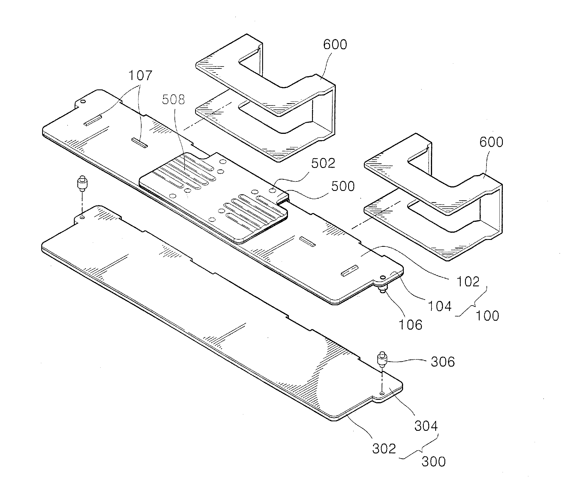
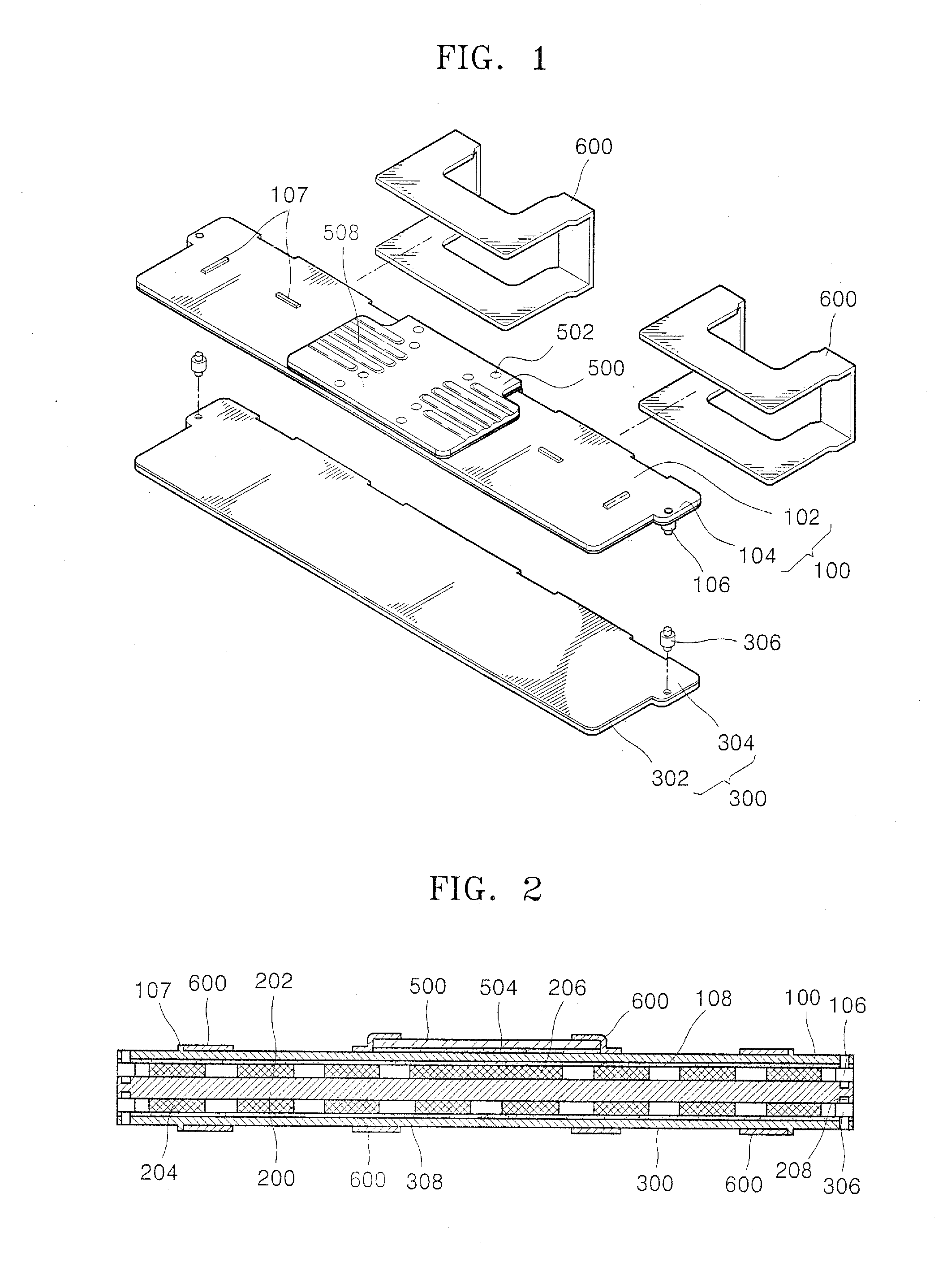
[0029]FIG. 1 is a dissected perspective view illustrating a heat sink according to an embodiment of the present invention. FIG. 2 is a cross-sectional view of the heat sink illustrated in FIG. 1, according to an embodiment of the present invention.

[0030]Referring to FIGS. 1 and 2, the heat sink includes a first heat spreader 100, a second heat spreader 300, a third heat spreader 500 disposed on the first heat spreader 100, a first guide pin 106 and a second guide pin 306 respectively installed on the first and second heat spreaders 100 and 300 and inserted into an object 200 to be cooled, and a coupling unit 502 closely adhering and coupling the first and second heat spreaders 100 and 300 to the object 200 to be cooled.

[0031]The first heat spreader 100 is a thin layer facing and contacting a first component 202 disposed on an upper surface of the object 200 to be cooled and directs away heat generated in the first component 202. The second heat spreader 300 is a thin layer facing an...

embodiment 2

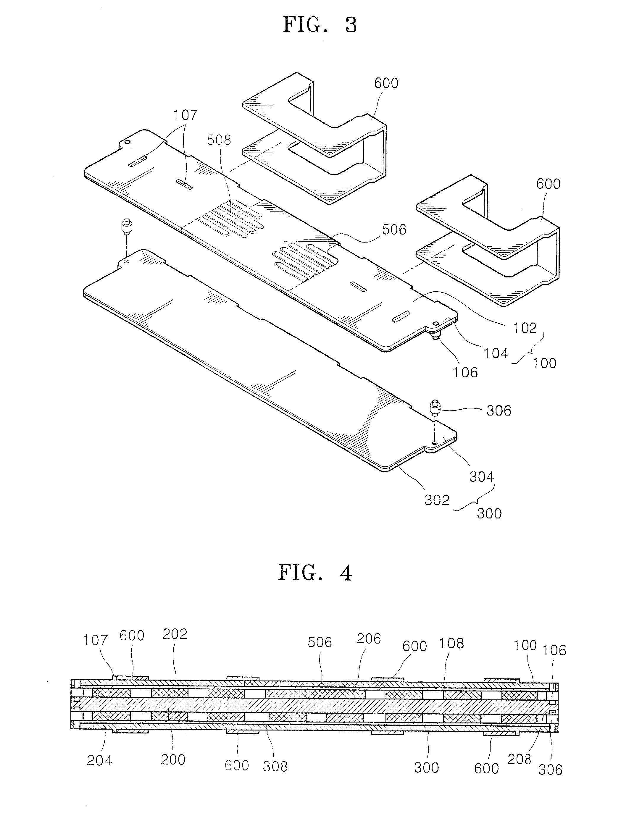
[0042]FIG. 3 is a dissected perspective view illustrating a heat sink according to another embodiment of the present invention. FIG. 4 is a cross-sectional view of the heat sink illustrated in FIG. 3, according to an embodiment of the present invention.

[0043]In detail, the heat sink according to the current embodiment of the present invention is substantially the same as the heat sink of FIG. 1 except that the third heat spreader 500 (shown in FIG. 2) is not installed on the surface of the first heat spreader 100. In FIGS. 3 and 4, the reference numerals identical to those of FIGS. 1 and 2 refer to identical components, and descriptions of the identical components, for example, the connection relationship and the effects, will be omitted.

[0044]Referring to FIGS. 3 and 4, even though the third heat spreader 500 is not installed in a center portion 506 on the surface of the first heat spreader 100, the heat sink of the current embodiment of the present invention can easily emit heat g...

embodiment 3

[0046]FIG. 5 is a dissected perspective view illustrating a heat sink according to another embodiment of the present invention. FIG. 6 is a cross-sectional view of the heat sink illustrated in FIG. 5, according to an embodiment of the present invention.

[0047]In detail, the heat sink according to the current embodiment of the present invention is substantially identical to the heat sink of FIG. 1 except that first and second guide pins 106a and 306a of the current embodiment have a different shape than the first and second guide pins 106 and 306 of the heat sink of FIG. 1. In FIGS. 5 and 6, the reference numerals identical to those of FIGS. 1 and 2 refer to identical components, and descriptions of the identical components, for example, the connection relationship and the effects, will be omitted. In addition, a third heat spreader 500 is included in FIGS. 5 and 6 but may not be included according to necessity.

[0048]Referring to FIGS. 5 and 6, first and second guide pins 106a and 306...


PUM


Abstract

Provided are a heat sink and a memory module using the heat sink. In one embodiment, the heat sink includes a first and second guide pin respectively disposed in first and second heat spreaders placed around an object to be cooled. The first and second guide pins help prevent misalignment problems from occurring between the first and second heat spreaders, as well, as helping prevent the first and second heat spreaders from contacting each other when the first and second heat spreaders are pressed by pressure applied from the outside.

Description

CROSS-REFERENCE TO RELATED PATENT APPLICATION[0001]This application claims the benefit of Korean Patent Application No. 10-2006-0092453, filed on Sep. 22, 2006 in the Korean Intellectual Property Office, the disclosure of which is incorporated herein by reference.BACKGROUND[0002]1. Field of the Invention[0003]The present invention relates to a heat sink and a memory module using the heat sink, and more particularly, to a heat sink that can be applied to a semiconductor package, and a memory module using the heat sink.[0004]2. Description of the Related Art[0005]In general, the driving speed of a semiconductor package, for example, a ball array semiconductor package, is high resulting in a substantial amount of heat radiation. To maintain performance this heat generated in the semiconductor package must be dissipated. Also in general, a memory module in which a plurality of semiconductor packages (semiconductor chips) are mounted on a printed circuit board (PCB) is used to increase m...

Claims


Application Information

Patent Timeline
IPC IPC(8): H05K7/20
CPCH01L23/4093H01L2924/0002H01L2924/00H05K7/20
Inventor PARK, CHANG-YONGKIM, YONG-HYUNCHUN, KWANG-HOOH, HYUN-JONG
Owner SAMSUNG ELECTRONICS CO LTD
Why Eureka
Try Eureka