Torque compensation method and system for DC brushless motor

Inactive Publication Date: 2008-03-27
SUNPLUS TECH CO LTD
View PDF5 Cites 8 Cited by
  • Summary
  • Abstract
  • Description
  • Claims
  • Application Information

AI Technical Summary

Benefits of technology

[0006]The present invention provides a torque compensation system, comprising: a DC brushless motor, having an asymmetric load; a shunt resistor, having a first terminal connected to a ground; a DC/AC inverter, connected to a DC voltage by a first power input terminal and connected to a second terminal of shunt resistor by a second power input terminal, for generating a plurality of driving currents to the DC brushless motor in response to a plurality control signals, wherein the plurality of driving currents start from the DC voltage and then flow through the DC brushless motor and through the shunt resistor to reach the ground; a position detecting circuit, for generating a plurality of position signals in response to a rotating position from the DC brushless motor; and, a control unit, for determining a plurality of absolute rotor positions in response to the position signals, wherein the control unit has a sampling terminal connected to the second power input terminal for calculating an average current and an instant current flowing through the shunt resistor and adjusts the control signals in response to the average current and the instant current.
[0007]The present invention provides a torque compensation method applied to a DC brushless motor coupled with an asymmetric load, comprising steps of: determining a plurality of absolute rotor positions in response to a plurality of position signals; and, detecting an average current and an instant current flowing through a protecting resistor when the DC brushless motor in one of the plurality of absolute rotor positions and adjusting a plurality of control signals for approaching the instant current to the average current in response to the difference of the average current and the instant current; wherei

Problems solved by technology

The irregularity of the load thus causes torque ripple in the controlling motor.
Further, when the motor is driven by a fixed voltage, problems such as vibration and noise are resulted from the asymme

Method used


Image

  • Torque compensation method and system for DC brushless motor
  • Torque compensation method and system for DC brushless motor
  • Torque compensation method and system for DC brushless motor

Examples


Embodiment Construction

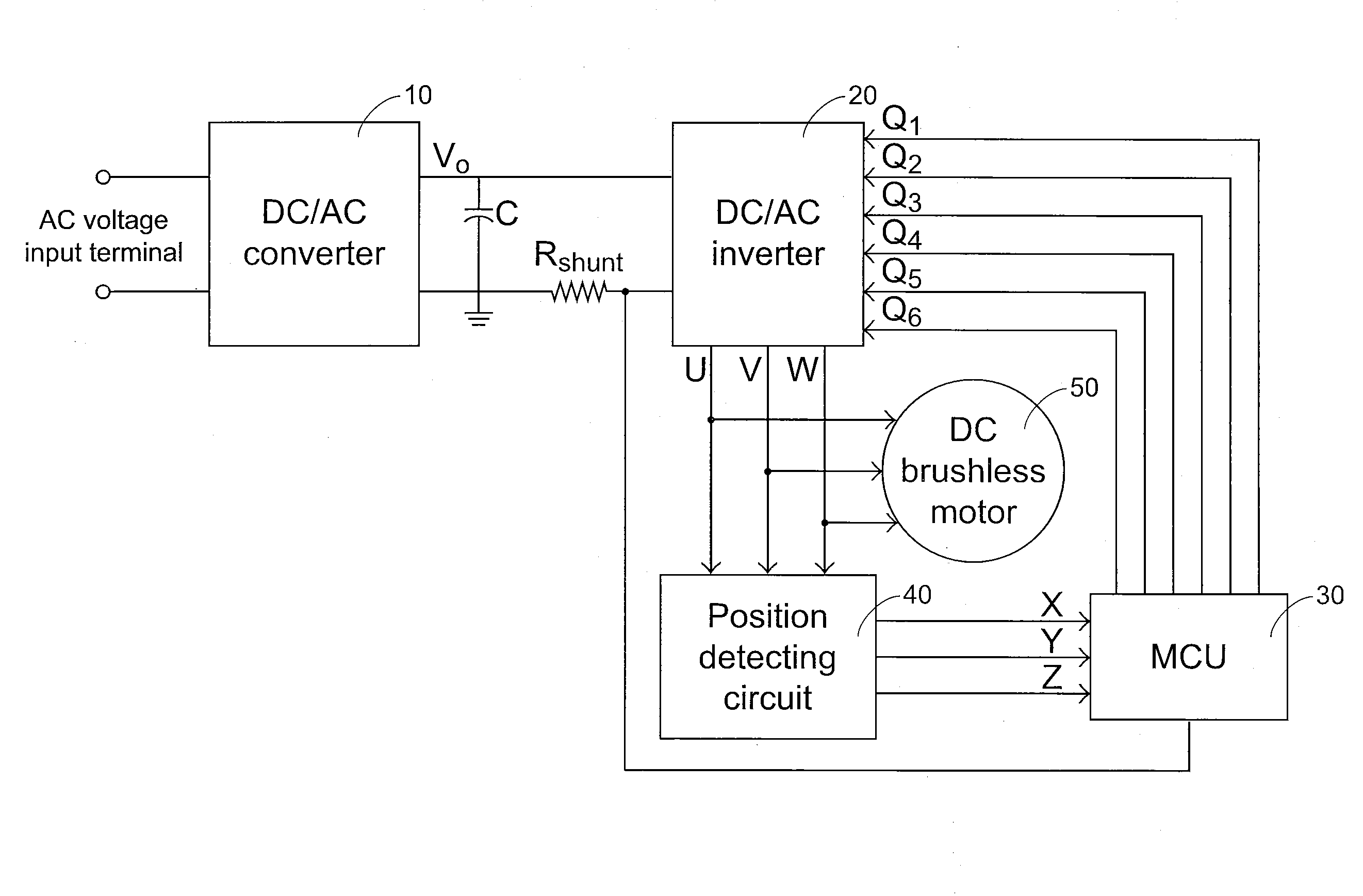
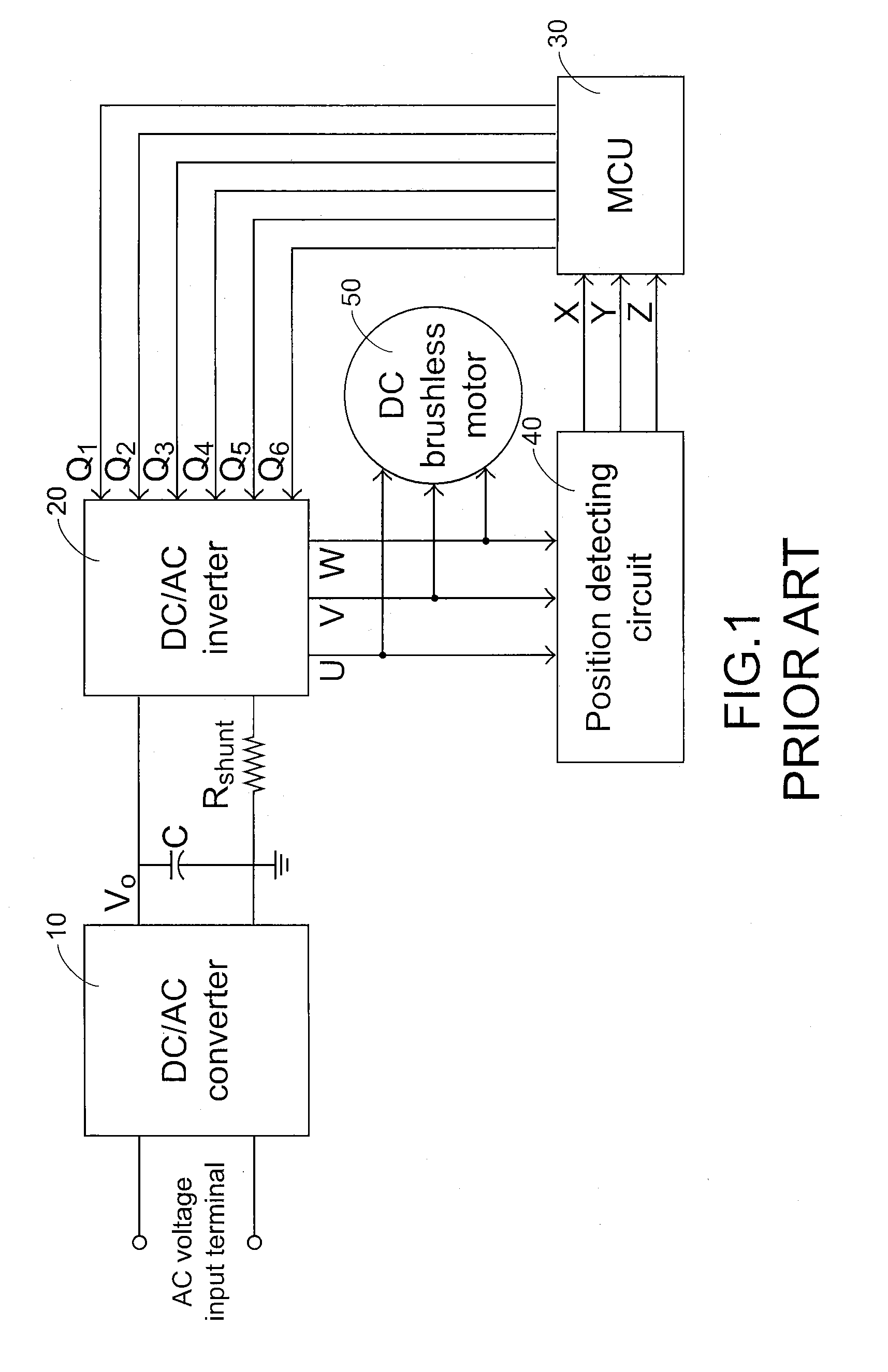
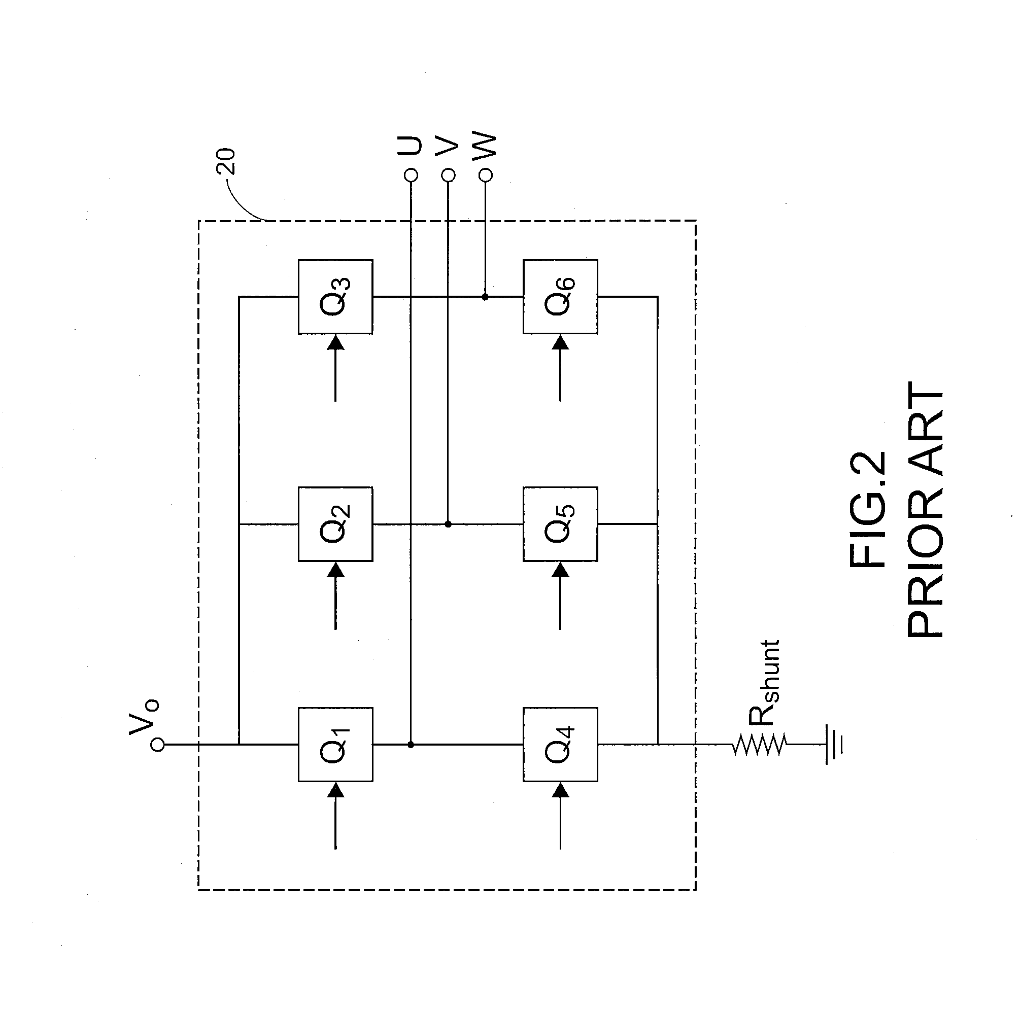
[0017]Please refer to FIG. 1, which illustrates the block diagram of the conventional DC brushless motor control system. First, an AC voltage is inputted into a DC / AC converter 10 and the DC / AC converter 10 generates a DC output voltage (VO) which is stabilized by a capacitor (C) and then provided to a power input of the DC / AC inverter 20; the first power input terminal of the DC / AC inverter 20 is connected to the aforesaid VO, and a protecting resistor called a shunt resistor (Rshunt) is usually connected between the ground and the second power input terminal of the DC / AC inverter 20. Further, a micro control unit (MCU) 30 can provide several control signals to the DC / AC inverter 20 to enable the DC / AC inverter 20 to generate three phases driving currents (U, V, W) outputting to the three-phase DC brushless motor 50 and then make three-phase DC brushless motor 50 rotate. The position detecting circuit 40 is coupled to the three phases driving currents outputting terminals for gener...


PUM


Abstract

A torque compensation method and system for a DC brushless motor. When the DC brushless motor coupled with an asymmetric load is rotating, the difference between an instant current and an average current of a shunt resister is an index of adjusting control signals within an absolute rotor position for the purpose of approaching the corresponding instant current to the average current.

Description

FIELD OF THE INVENTION[0001]The present invention relates to a torque compensation method and system for a DC brushless motor, and more particularly to a torque compensation method and system for a DC brushless motor coupled with an asymmetric load.BACKGROUND OF THE INVENTION[0002]As known in the art, a DC brushless motor is similar in performance and application to a brush-type DC motor. Both have a speed vs. torque curve, which is linear or nearly linear. The motors differ, however, in construction and method of commutation. A brush type permanent magnet DC motor usually consists of an outer permanent magnet field and an inner rotating armature windings to maintain rotation. A DC brushless motor has a wound stator, a permanent magnet rotor assembly and a sensing device to sense the rotating position. The sensing device provides signals for electronically switching (commutating) the stator windings in the proper sequence to maintain rotation of the magnet rotor.[0003]In the family ...

Claims


Application Information

Patent Timeline
IPC IPC(8): H02P7/29
CPCH02P6/14H02P6/08H02P6/10
Inventor HUANG, CHIH-MING
Owner SUNPLUS TECH CO LTD
Why Eureka
Try Eureka