Machining line

a technology of machining line and machining machine, which is applied in the direction of automatic workpiece supply/removal, pile separation, measurement/indication equipment, etc., can solve the problems of inconvenient energy consumption and space waste, and achieve the effect of reducing energy consumption

Inactive Publication Date: 2008-03-27
GROB WERKE & K G
View PDF1 Cites 9 Cited by
  • Summary
  • Abstract
  • Description
  • Claims
  • Application Information

AI Technical Summary

Benefits of technology

[0009] Coming from the state of the art described before it is an object of this in...

Problems solved by technology

This concept proven in the state of the art, however, is inconvenient with respect of the consumption of energy.
The smallest distance between the ind...

Method used


Image

  • Machining line
  • Machining line
  • Machining line

Examples


Embodiment Construction

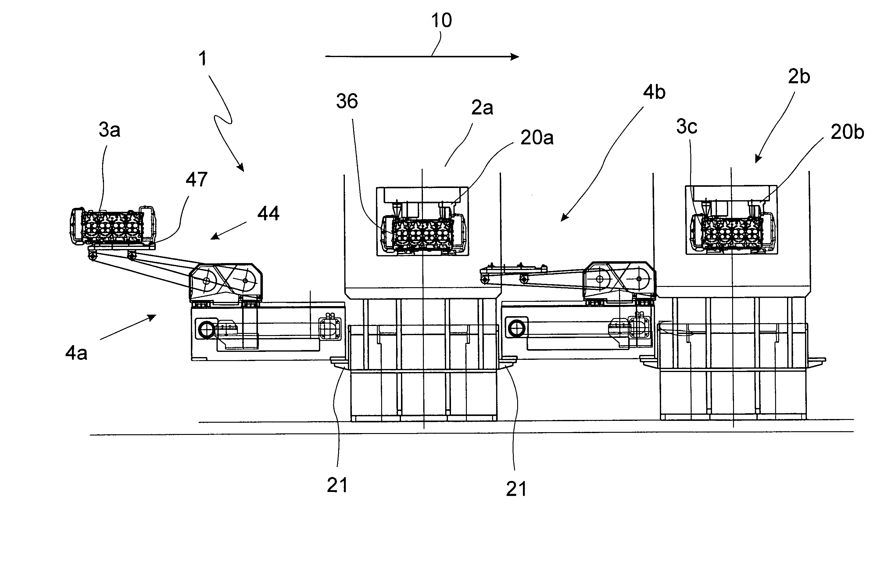
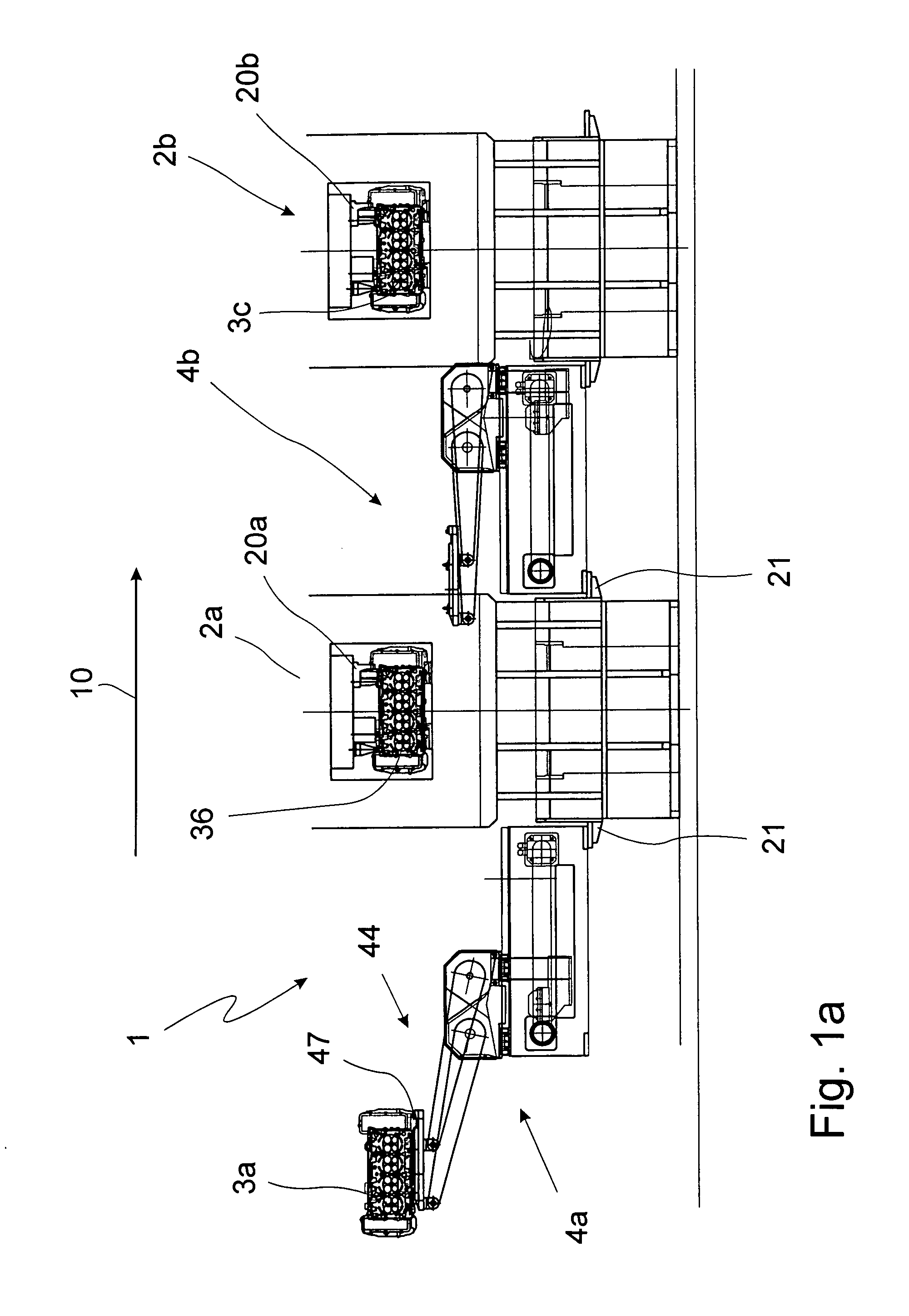
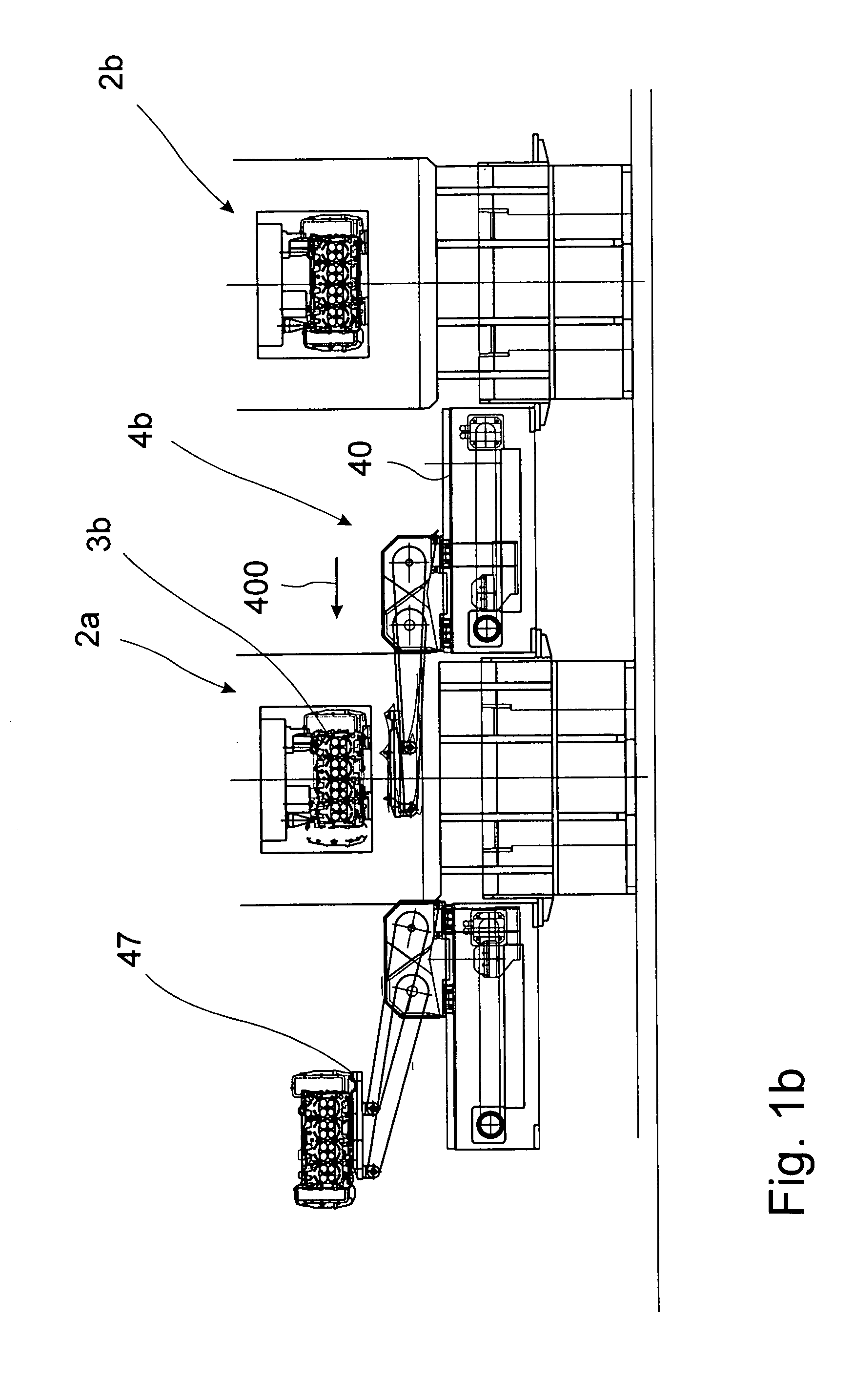
[0051] In FIG. 1a a schematic construction of a machining line 1 according to the invention is shown. The machining line comprises here a multitude of machining stations 2a, 2b arranged in the direction of movement 10 of the work pieces 3a, 3b, 3c. Between the individual machining stations 2a, 2b and so on conveying devices 4a, 4b are provided which are each driven and working independently from each other. The conveying devices 4a, 4b are supported on consoles 21 at the machining stations 2a, 2b.

[0052] The direction of movement 10 runs on the sheet from the left to the right. Thus the consequence is that the work piece 3a approached by the first conveying device 4a has to be set in as the next one in the machining station 2a. This can, of course, only be carried out when the work piece 3b in the station has been conveyed out of this first machining station 2a by means of the second conveying device 4b. This is not possible before the work piece 3b has left the second machining sta...


PUM

PropertyMeasurementUnit
Timeaaaaaaaaaa
Angleaaaaaaaaaa
Heightaaaaaaaaaa

Abstract

The invention refers to a machining line, in particular a transfer line or assembly line, comprising a multitude of machining stations arranged one after the other in the direction of machining, and the machining station serves for machining work pieces, wherein at least one machining station is designed as special station. The invention is characterised by the fact that between two adjoining machining stations one conveying device each is provided.

Description

BACKGROUND OF THE INVENTION [0001] The invention refers to a machining line, in particular a transfer line or assembly line, comprising a multitude of machining stations arranged one after the other in the direction of machining, and the machining station serves for the machining of work pieces, wherein at least one machining station is designed as special machine. [0002] Machining lines as described in the beginning are, as mentioned, known sufficiently, for example, as transfer lines in the state of the art. [0003] Transfer lines are characterised here by the fact that the work pieces are machined one after the other by machining stations designed as special machining tools, and the conveying or transfer of the individual work pieces between the individual machining stations is carried out by a transfer rod or a transfer girder for all work pieces simultaneously. This concept proven in the state of the art, however, is inconvenient with respect of the consumption of energy. Becaus...

Claims


Application Information

Patent Timeline
IPC IPC(8): B65G47/24B65H11/00
CPCB23Q7/04Y10T29/5124B23Q41/02B23Q7/043B23Q7/046B23Q7/14B23Q2707/00
Inventor GROB, BURKHART
Owner GROB WERKE & K G
Why Eureka
Try Eureka