Bond line forming method

a technology of bond line and forming method, which is applied in the manufacture of final products, machines/engines, wind energy generation, etc., can solve the problems of increasing the cost and weight of the rotor blade, and using uncontrollable force to assemble the blade shell

Active Publication Date: 2008-03-27
GENERAL ELECTRIC CO
View PDF10 Cites 78 Cited by
  • Summary
  • Abstract
  • Description
  • Claims
  • Application Information

AI Technical Summary

Problems solved by technology

Thus, an uncontrolled force is used to assemble the blade shells.
Furthermore, a larg

Method used


Image

  • Bond line forming method
  • Bond line forming method
  • Bond line forming method

Examples


Embodiment Construction

[0022]Reference will now be made in detail to the various embodiments of the invention, one or more examples of which are illustrated in the figures. Each example is provided by way of explanation of the invention, and is not meant as a limitation of the invention. For example, features illustrated or described as part of one embodiment can be used on or in conjunction with other embodiments to yield yet a further embodiment. It is intended that the present invention includes such modifications and variations.

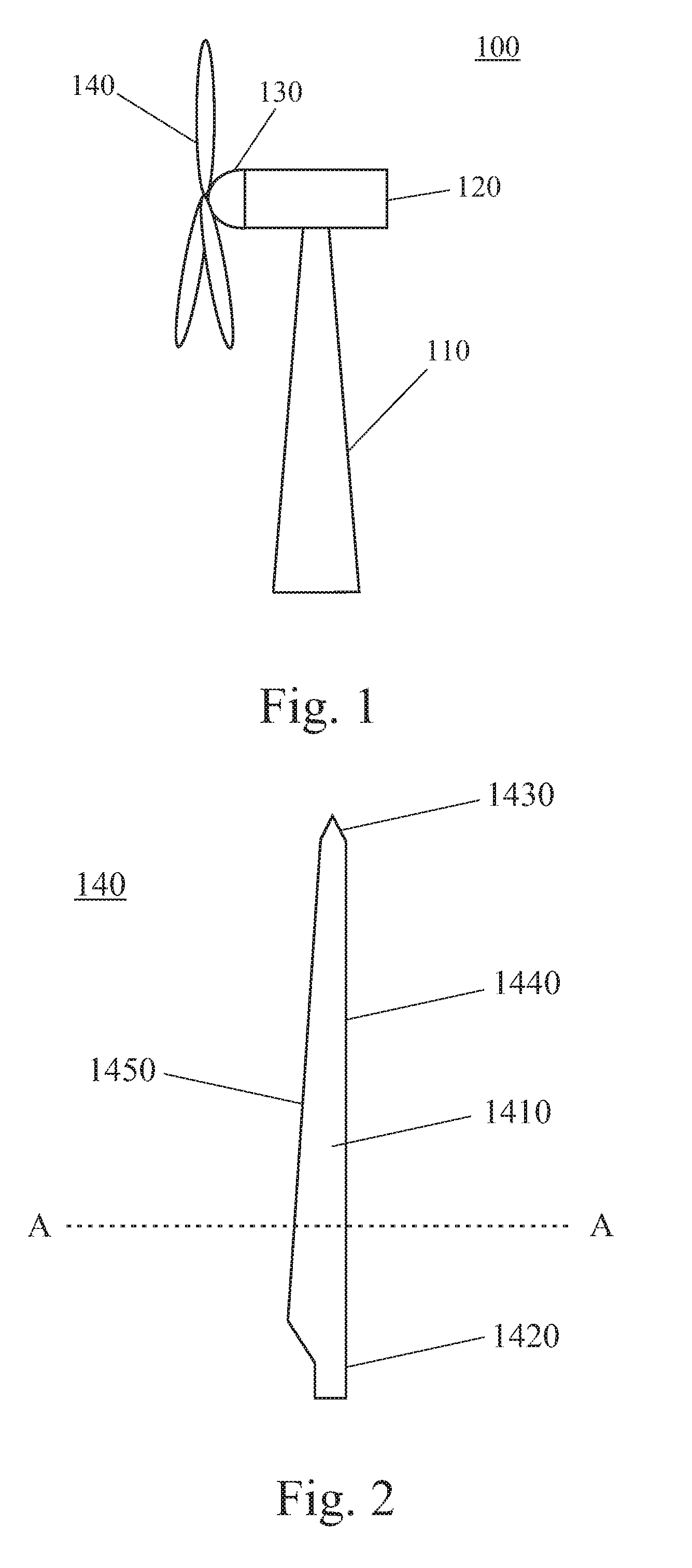
[0023]FIG. 1 is a schematic view of a wind turbine 100. Wind turbine 100 has a tower 110 on which a machine nacelle 120 is mounted. Typically, machine nacelle 120 houses an electric generator, a gear box and a turbine control device (not shown). A wind rotor for converting kinetic wind energy into rotational energy is mounted to one end of nacelle 130. The wind rotor includes a hub 130 mounted to nacelle 130 in a rotatable manner so that it can rotate about a horizontal axis. F...


PUM

PropertyMeasurementUnit
Adhesivityaaaaaaaaaa

Abstract

A method for forming a bond between a first and a second shell of a blade is provided. The method comprises the steps of forming a cavity between said first and second blade shells and filling an adhesive into said cavity to form a bond line between said first and second blade shells.

Description

BACKGROUND OF THE INVENTION[0001]The present invention relates to the formation of bond lines between two components to be bonded together and, particularly, to the formation of a bond line between two shells of a wind turbine rotor blade.[0002]Wind power has attracted much attention during recent years as an alternative source of energy. Wind turbines are used to convert the kinetic wind energy into electric power. For this purpose, utility-class wind turbines have wind rotors which are usually equipped with three huge rotor blades to extract kinetic energy from the wind. Typical lengths for these rotor blades range between 10 and 100 meters. There exists different rotor blade designs but typically the rotor blades are made of fiber-reinforced materials, e.g. glass fiber, carbon fiber, organic aramide fibers or the like. Furthermore, wind turbine rotor blades are typically of a composite design, i.e. the blade body is manufactured from two blade shells which are bonded together.[00...

Claims


Application Information

Patent Timeline
IPC IPC(8): B64C11/24
CPCB29C65/1406B29C66/636B29C65/542B29C65/544B29C66/322B29C66/54B29L2031/082B29L2031/085F03D1/0675F05B2230/20Y02E10/721B29C65/4865B29C66/543B29C65/1435B29C65/1483B29C65/4845B29C65/4835B29C65/485B29C65/00B29C66/7212B29C66/721B29C66/71B29C66/1142Y02E10/72Y02P70/50B29K2307/04B29K2309/08B29K2277/10B29K2077/10
Inventor VAN BREUGEL, SJEFBAKHUIS, WILLEMBILLEN, ANDY
Owner GENERAL ELECTRIC CO
Why Eureka
Try Eureka