Control Unit Heat Management

Active Publication Date: 2008-03-27
FORD GLOBAL TECH LLC
View PDF12 Cites 54 Cited by
  • Summary
  • Abstract
  • Description
  • Claims
  • Application Information

AI Technical Summary

Benefits of technology

[0006]In this way, it is possible to increase the heat transfer from

Problems solved by technology

As such, it is possible that there may an undesirable temperature rise due to heat buildup in the ECU, which may in turn cause degradation of the ECU and thus engine or other vehicle operation.
As such, this may result in insufficient cooling of the ECU and potentially increasing a possibility of heat relat

Method used


Image

  • Control Unit Heat Management
  • Control Unit Heat Management
  • Control Unit Heat Management

Examples


Embodiment Construction

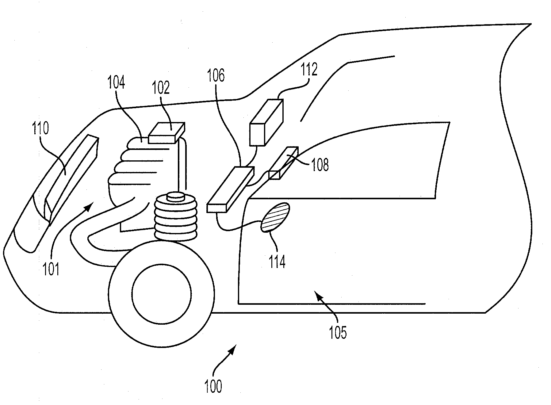
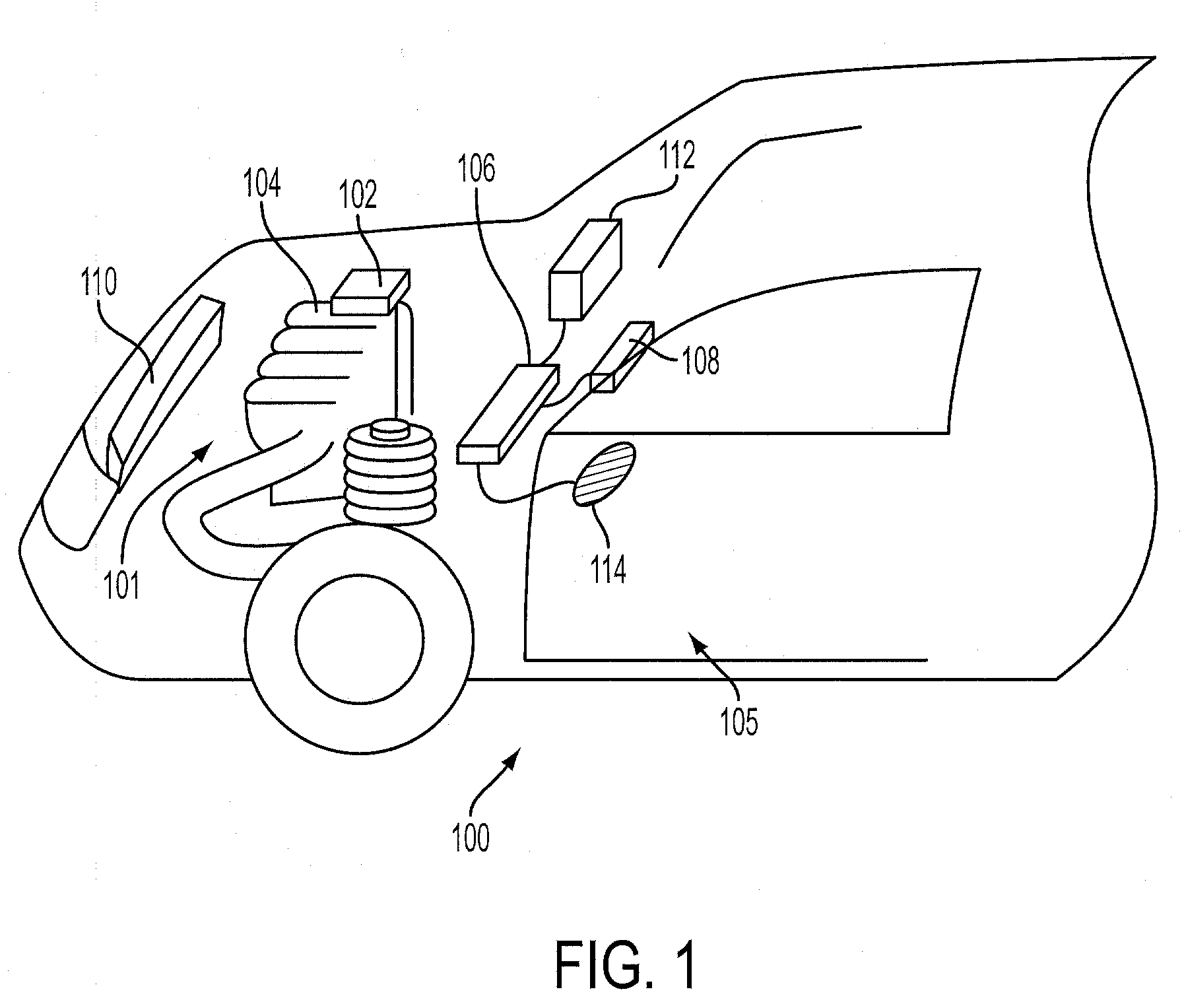
[0013]FIG. 1 shows the front part of automobile 100 with an engine compartment 101 having an internal combustion engine 104. Engine 104 may be a gasoline or diesel engine, such as a direct injection engine as shown in FIG. 6. An engine control unit (ECU) is designated as 102, where the ECU controls one or more function of the engine, such as fuel injection timing and / or amounts, ignition timing, and various others. The ECU may be located in various positions that may be proximate to or adjacent the engine or engine compartment. In the example of FIG. 1, the ECU is located adjacent and on top of the engine in the engine compartment 101. However, the ECU may also be located behind the engine, or proximate and / or adjacent to the passenger compartment, Additionally, the ECU may be located in, upstream of, downstream of, or near vents, such as a recirculation vent 106, leading to or from the passenger compartment, and / or in a position in which airflow around or near the ECU is affected a...


PUM


Abstract

A method of cooling an engine control unit (ECU) coupled to an engine in a vehicle having a cabin climate control system, comprising of operating the vehicle cabin climate control system according to a customer-based climate control setting during a first operating condition, and overriding said customer-based setting during a second operating condition including an ECU over-temperature condition.

Description

BACKGROUND AND SUMMARY[0001]Internal combustion engines of an automobile may utilize an engine control unit (ECU) for electronically controlling engine operation. For example, the ECU may control the engine ignition system the engine as well as other vehicle or engine components, and may also be coupled to a plurality of sensors. In one example, the ECU may be located near or in the engine compartment such that significant heat energy generated by the engine and related components may be transferred to the ECU. As such, it is possible that there may an undesirable temperature rise due to heat buildup in the ECU, which may in turn cause degradation of the ECU and thus engine or other vehicle operation. Further, this heat buildup may be exacerbated by conduction or other transfer of heat from the systems adjacent to an enclosed space in which the ECU is located, and by the heat generated from the ECU itself.[0002]To control or reduce ECU temperature, various forms of heat management m...

Claims


Application Information

Patent Timeline
IPC IPC(8): B60H1/00B24D13/00
CPCB60H1/00735F01P2050/30B60H2001/00614B60H1/00964B60H1/32F01P1/06F02B3/10
Inventor BRYANT, BRUCESURESHBABU, SURESHVAN NIEUWSTADT, MICHIEL J.
Owner FORD GLOBAL TECH LLC
Why Eureka
Try Eureka