Slide member

Inactive Publication Date: 2008-03-27
HITACHI LTD
View PDF2 Cites 21 Cited by
  • Summary
  • Abstract
  • Description
  • Claims
  • Application Information

AI Technical Summary

Benefits of technology

[0019]According to the present invention, it is possible to provide a slide member comprisin

Problems solved by technology

However, such conventional slide members comprising a diamond-like carbon layer have a problem in that they do not always provide a low coefficient of friction under the unlubricat

Method used


Image

  • Slide member
  • Slide member
  • Slide member

Examples


example 1

[0044]The disk substrate 12 of an alloy (chromium molybdenum steel) containing Fe, Cr and Mo was carburized to have a Rockwell C scale surface hardness (HRC) of 58 or more, and was dressed to have an average surface roughness (Ra) of 0.1 μm or less. Then, a coating layer 13 was formed by an UBMS method while introducing inert and hydrocarbon gases so as to have an Al content of 1.88 at. %.

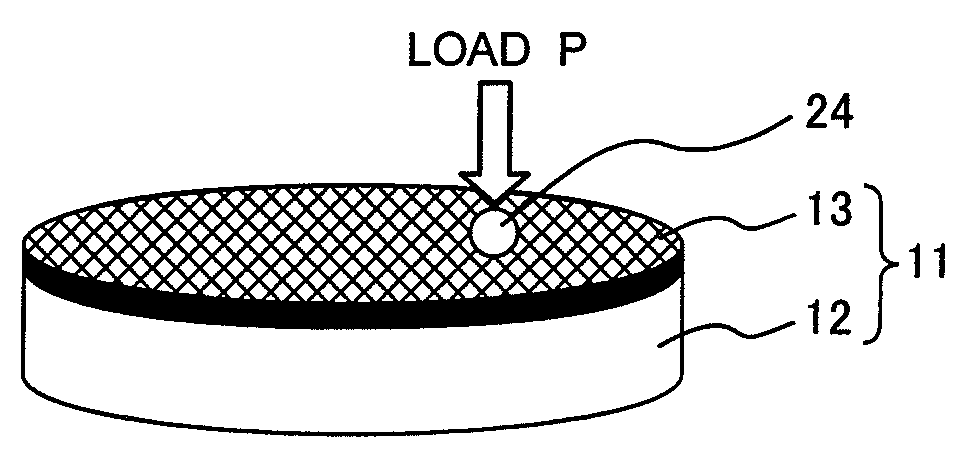
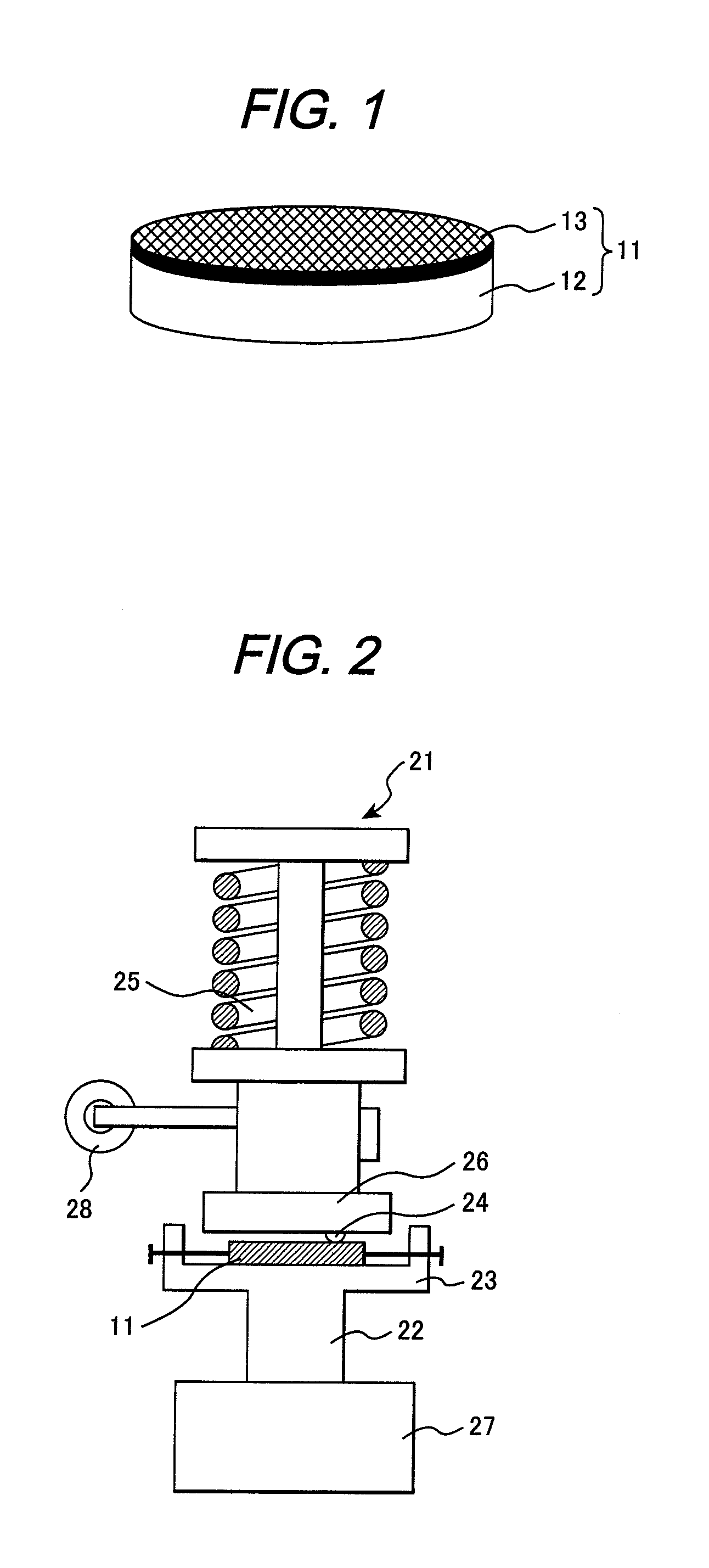
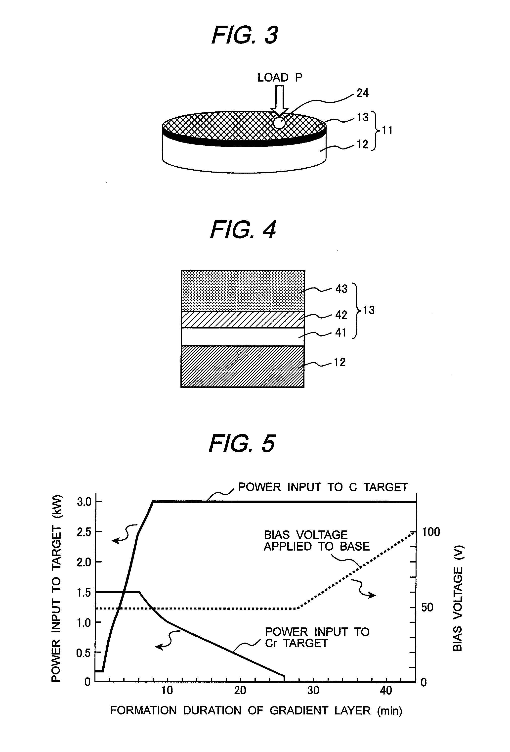
[0045]FIG. 4 is a schematic illustration showing a partial cross sectional view of a test specimen 11 comprising the coating layer 13 formed on the substrate 12. As shown in FIG. 4, the coating layer 13 has a Cr intermediate layer 41, an outermost surface layer 43 and a gradient layer 42 disposed between the intermediate layer 41 and the outermost surface layer 43. When forming the gradient layer 42, the powers input to the Cr and C targets and bias voltage applied to the substrate were controlled as shown in FIG. 5. FIG. 5 is a graph indicating a method for controlling with time powers input to Cr...


PUM

PropertyMeasurementUnit
Thicknessaaaaaaaaaa
Thicknessaaaaaaaaaa
Pressureaaaaaaaaaa

Abstract

A slide member according to the present invention includes: a substrate of at least one element selected from a group made up of V, Cr, Fe, Co, Ni, Zr, Nb, Mo, Ta, W, Ir and Pt; a gradient layer containing chromium and carbon formed on the substrate; and a hard carbon coating layer formed on the gradient layer, in which the graded layer has a component conformation comprising a gradually decreasing chromium concentration and gradually increasing carbon concentration from the substrate side to the hard carbon coating layer side, and the hard carbon coating layer contains aluminum.

Description

CLAIM OF PRIORITY[0001]The present application claims priority from Japanese application serial no. 2006-259866 filed on Sep. 26, 2006, the content of which is hereby incorporated by reference into this application.BACKGROUND OF THE INVENTION[0002]1. Field of the Invention[0003]The present invention relates to slide members comprising a hard carbon coating with a low friction.[0004]2. Description of Related Art[0005]Hard carbon coatings generally have features of a high hardness, a smooth surface, excellent friction resistance, and a low coefficient of friction; and these excellent friction properties are attributed to their solid lubricity. Under unlubricated condition, the surface friction coefficient is 0.5 to 1.0 for the smooth surface of typical steel and approximately 0.4 for conventional surface treatment materials such as Ni—P or Cr plating, and TiN or CrN coating; while hard carbon coatings have a surface friction coefficient of approximately 0.12.[0006]Currently, by utiliz...

Claims


Application Information

Patent Timeline
IPC IPC(8): F16C33/12C23C14/34
CPCC23C14/0605C23C14/027
Inventor OKAMOTO, SHINYANAKASHIMA, SHOICHIBABA, NOBORUYAMAGUCHI, SHIZUKA
Owner HITACHI LTD
Why Eureka
Try Eureka