Hard coating for cutting tool

Active Publication Date: 2015-05-07
KORLOY
View PDF1 Cites 1 Cited by
  • Summary
  • Abstract
  • Description
  • Claims
  • Application Information

AI Technical Summary

Benefits of technology

[0016]According to a hard film for a cutting tool of the present invention, since various characteristics required for a hard film for a cutting tool, such as abrasion resistance, lubricant, toughness, chipping resistance, and oxidation resistance, may be evenly improved through a repeated stacking of a nano multi-layered structure formed by sequentially stacking a Ti and Al composite nitride layer commonly having excellent abrasion resistance and an adhesion to a base material, an Al, Ti and Cr composite nitride layer having excellent lubricant, an Nb or V composite nitride layer having excellent toughness and chipping resistance and also having improve

Problems solved by technology

Especially, since stainless steel, heat-resistant alloy steel, ductile cast iron and the like have a low thermal conductance compared to general steels, cutting heat is not emitted due to chips in a cutting and heat is concentrated on a cutting edge portion of the cutting tool, abrasion, seizure and exfoliation phenomena are easily generated on the cutting edge of the cutting tool due to a chemical reaction between the cutting tool and the wor

Method used


Image

  • Hard coating for cutting tool
  • Hard coating for cutting tool

Examples


Embodiment Construction

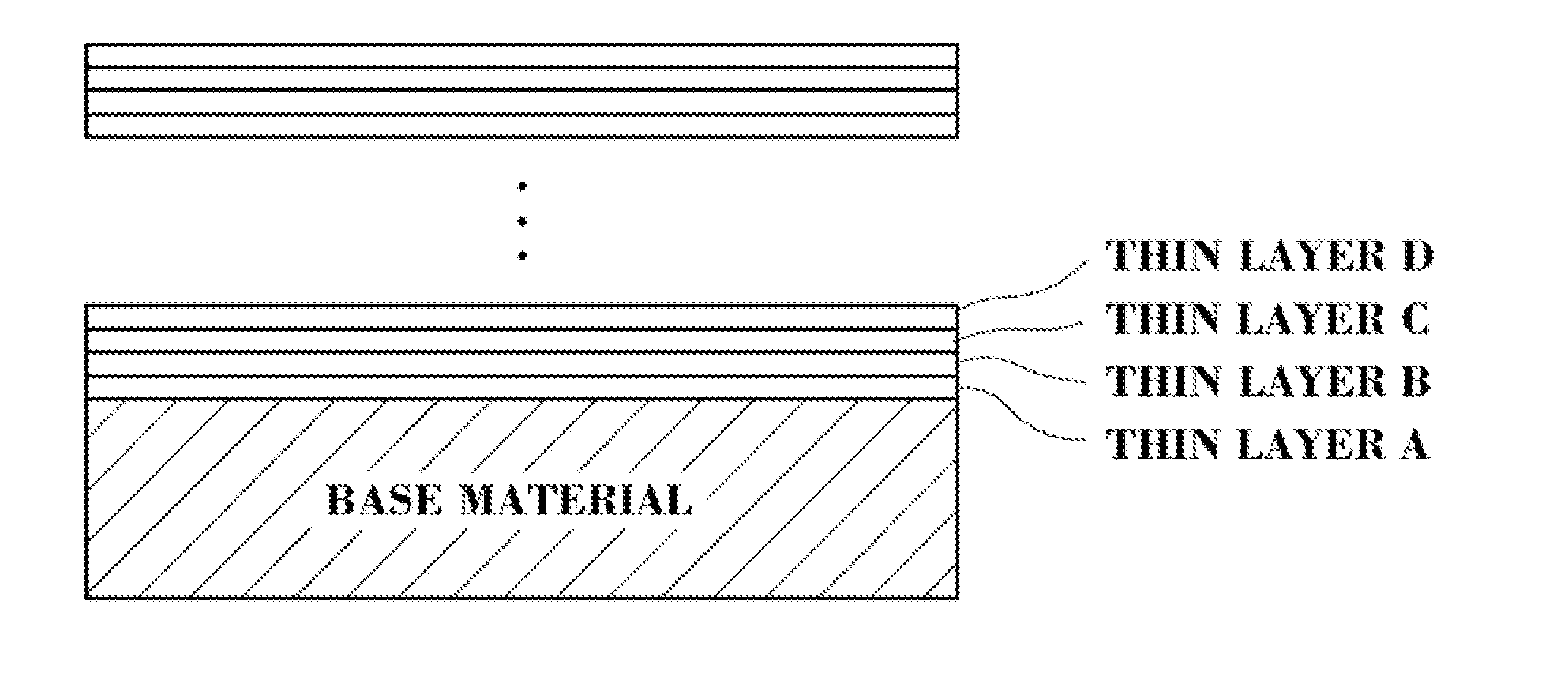
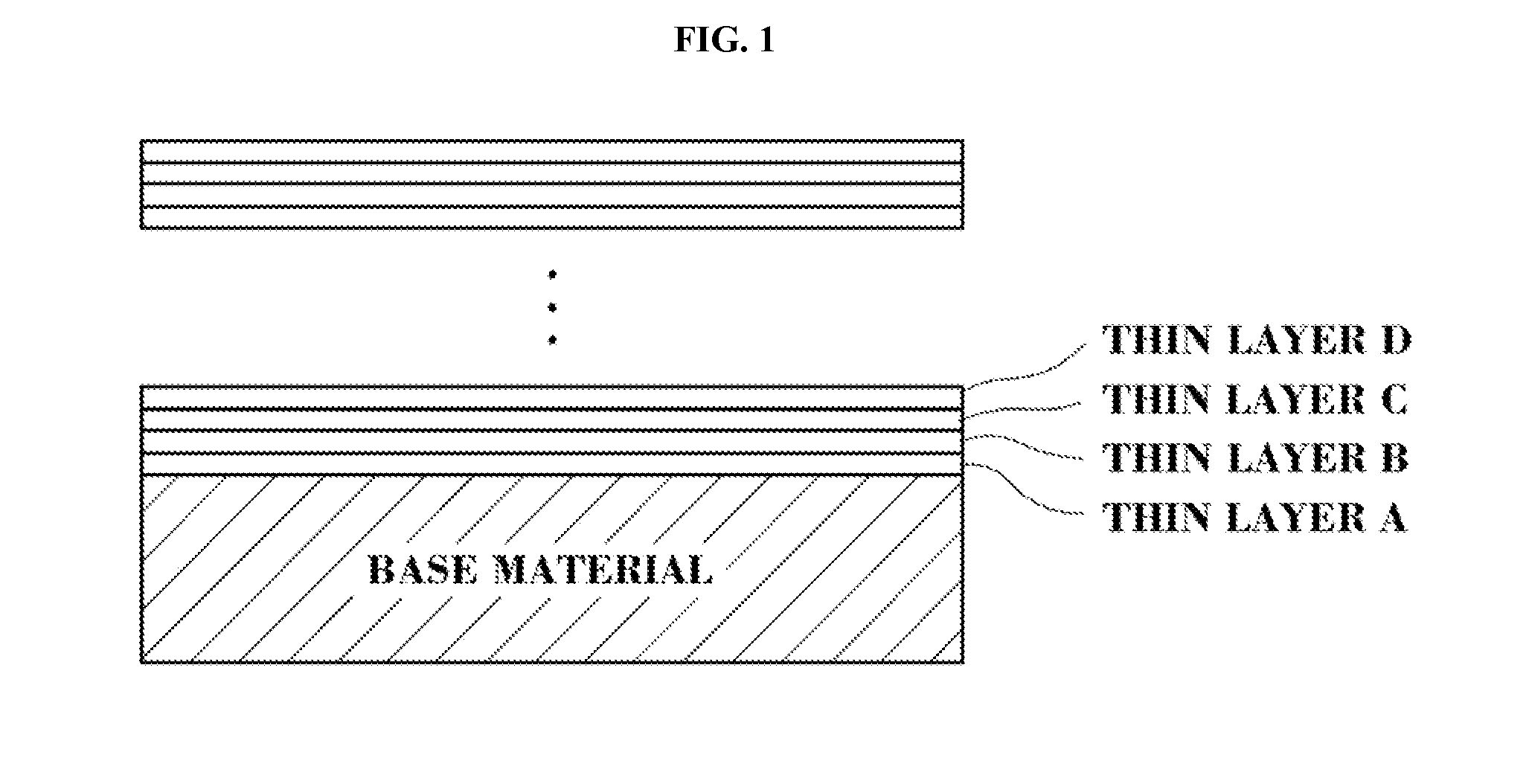
[0039]In the present invention, a hard film was coated on a surface of a hard base material of WC-10 wt % Co by using an arc ion plating method that is a physical vapor deposition (PVD), the hard base material including a cermet, high speed steel, an end mill, drill or the like. In the coating, a TiAl target, a AlTiCr target, an Nb or V target and an AlTiSi target were used with respect to a thin layer A, a thin layer B, a thin layer C and a thin layer D, respectively. An initial pressure was reduced to 8.5×10⁻⁵ Torr or less, and N2 was introduced as a reaction gas. A gas pressure for coating was 30 mTorr or less and preferably 20 mTorr or less, a coating temperature was 400° C. to 550° C., and a substrate bias voltage was applied in −20 V to −150 V in a coating. Of course, the coating condition may be different from that of Example of the present invention according to an equipment characteristic and condition.

[0040]In Example of the present invention, a TiAlN film that is an abras...


PUM

PropertyMeasurementUnit
Temperatureaaaaaaaaaa
Thicknessaaaaaaaaaa
Thicknessaaaaaaaaaa

Abstract

Provided is a hard film for a cutting tool formed on a surface of a base material, the hard film being comprised of a nano multi-layered structure comprising a thin layer A, a thin layer B, a thin layer C and a thin layer D or a structure in which the nano multi-layered structure is repeatedly stacked at least twice, wherein the thin layer A is comprised of Ti1-xAlxN (0.5≦x≦0.7); the thin layer B is comprised of Al1-y-zTiyCrzN (0.3≦y≦0.6 and 0<z≦0.3); the thin layer B is comprised of MeN (where Me is Nb or V); and the thin layer D is comprised of Al1-a-bTiaSibN (0.3≦a≦0.7 and 0<b<0.1).

Description

TECHNICAL FIELD[0001]The present invention relates to a hard film formed on a hard base material such as a hard metal, a cermet, a high-speed steel, an end mill, a drill, a cNB or the like that is used in a cutting tool, and more particularly, to a hard film for a cutting tool configured with a nano multi-layered structure including a thin layer A, a thin layer B, a thin layer C and a thin layer D or with a repeatedly stacked structure thereof, thus improving all of abrasion resistance, lubrication, toughness and oxidation resistance compared to an existing multi-layered thin film structure.BACKGROUND ART[0002]As the industry gradually advances toward fineness, speedup and mass production, it is required to improve cutting performance and life cycle of a cutting tool. Especially, since high heat of 900° C. or more is locally generated on a front end of the cutting tool rubbing with a workpiece in a rapid cutting of a workpiece having a high hardness and a cutting of a difficult-to-c...

Claims


Application Information

Patent Timeline
IPC IPC(8): C23C14/06
CPCC23C14/0641B32B15/01C23C14/14C23C14/32Y10T428/24975
Inventor PARK, JE-HUNKANG, JAE-HOONAHN, SEUNG-SUKIM, SUNG-HYUNLEE, SUNG-GUKIM, JUNG-WOOKAHN, SUN-YONGPARK, DONG-BOK
Owner KORLOY
Why Eureka
Try Eureka