Communication network system

Inactive Publication Date: 2008-04-03
SUMITOMO HEAVY IND LTD
View PDF7 Cites 43 Cited by
  • Summary
  • Abstract
  • Description
  • Claims
  • Application Information

AI Technical Summary

Benefits of technology

[0038]According to the communication network system in an embodiment of the invention, different communication networks are unified into one communication network so that sharing of the status information in the two networks and integrated management of the shared information can be carried out using the master controller. The integrated management of the shared information will ensure the reliability of the unified communication network system.
[0039]According to the communication network system in an embodiment of the invention, the master controller and the slave devices are connected to the common

Problems solved by technology

It is expected that the cost will be increased and the space for accommodating the cables will be increased.
However, in the case of the conventional communication network system, the development of a unified system for assigning the functions of the cryopump system controller to operate and control the pumps and the compressors to the master controller will require a very high cost.
It is not so realistic when such a restriction that a unified system must be developed only with

Method used


Image

  • Communication network system
  • Communication network system
  • Communication network system

Examples


Embodiment Construction

[0045]A description will be provided of the preferred embodiments of the present invention with reference to the accompanying drawings.

[0046]In the following, unifying different communication networks means that the different communication networks are linked together so that communication between the networks can be performed using a common communication protocol. For example, it means that the main buses of the two communication networks are combined together to form a common main bus, and communication between the networks on the common main bus is performed using the common communication protocol.

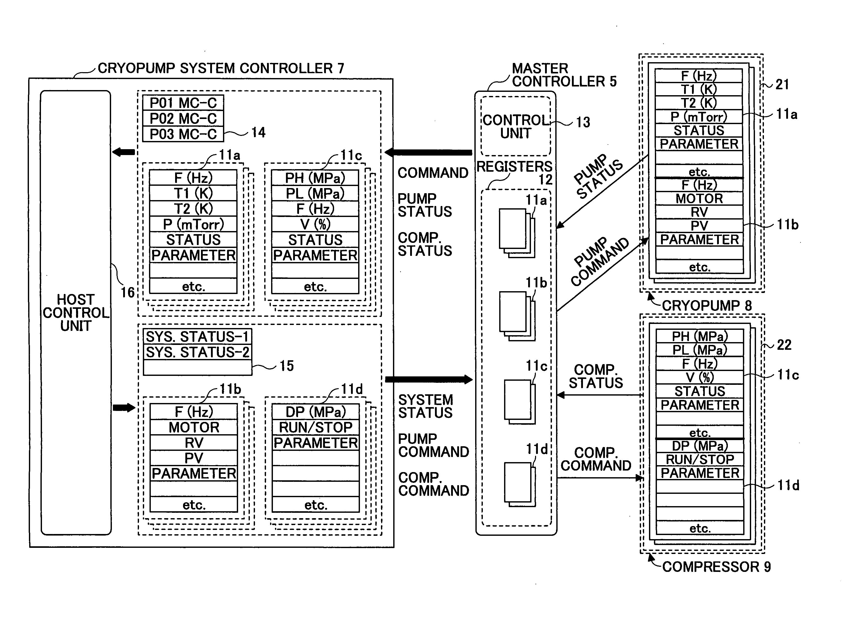
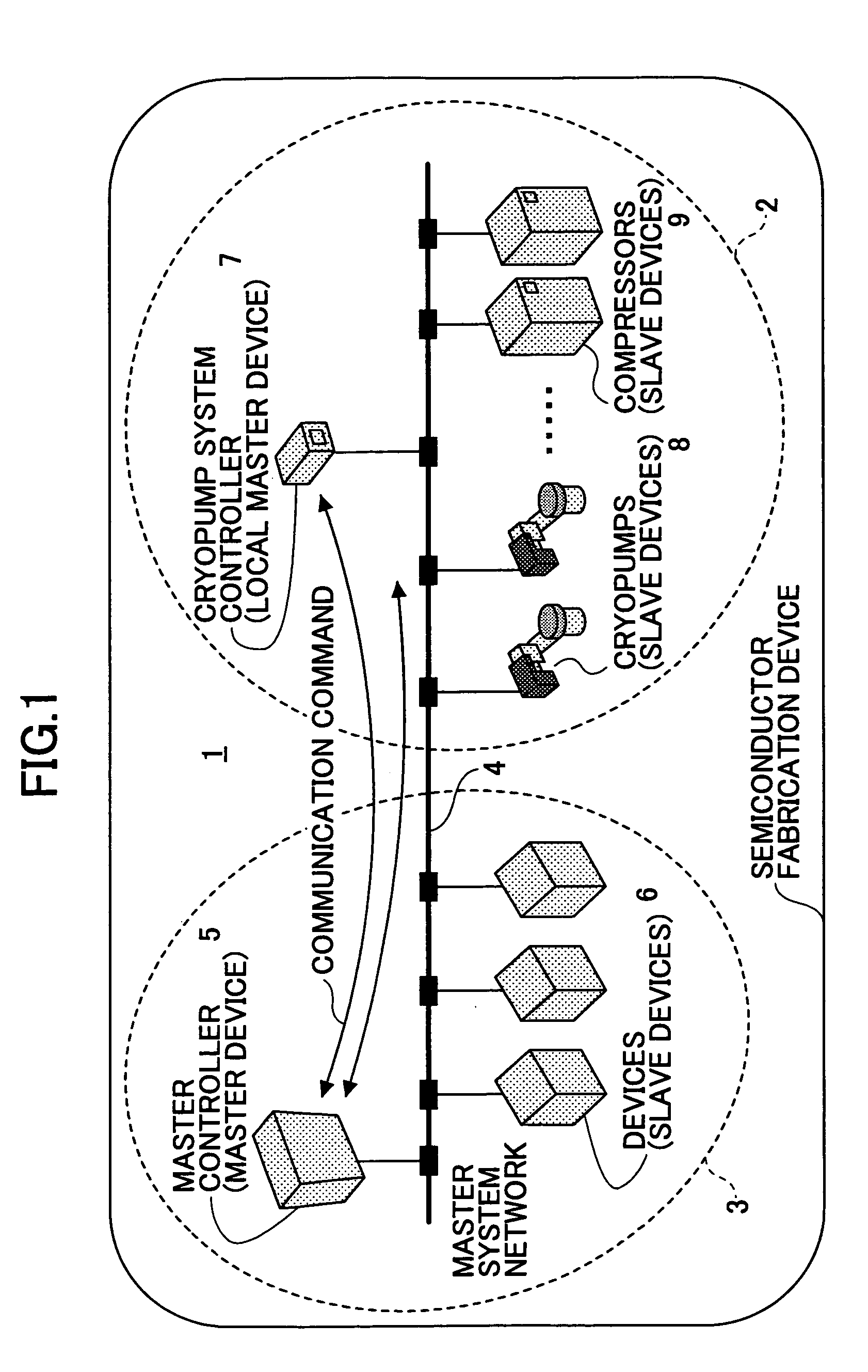
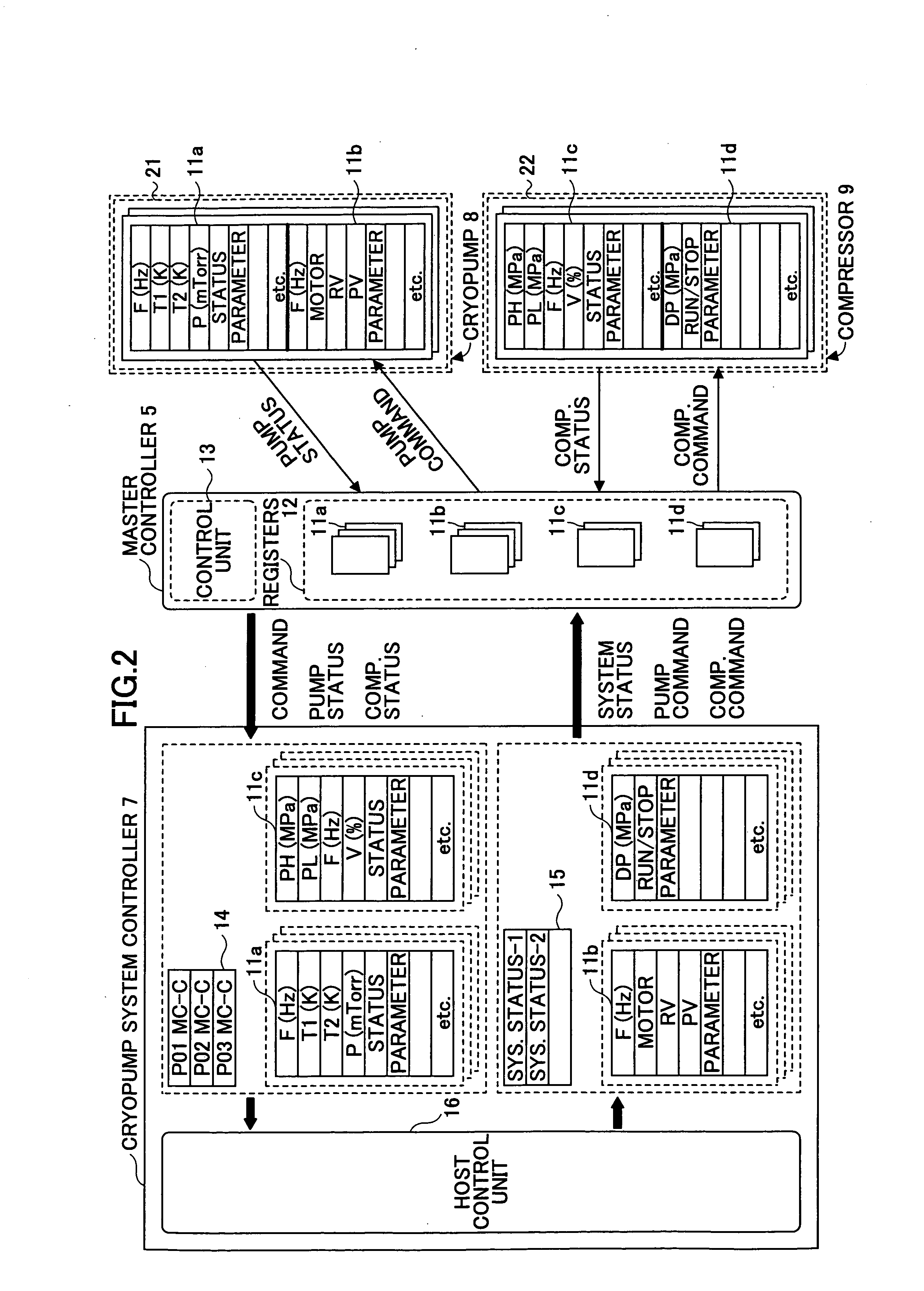
[0047]FIG. 1 shows the composition of the communication network system in an embodiment of the invention, which is appropriate for use in a semiconductor fabrication device.

[0048]As shown in FIG. 1, the communication network system 1 comprises a communication network of cryopump system 2 and a communication network of master system 3 which are linked in a parallel formation. Specificall...


PUM


Abstract

In a communication network system which unifies a system communication network and a master system communication network, each of a plurality of controlled devices is configured to transmit status data to a master controller and receive control data from the master controller so that the controlled device is operated based on the control data. The master controller comprises a control unit configured to receive status data of the controlled devices and transmit control data to the controlled devices, the control unit being configured to transmit the status data to a system controller and receive the control data from the system controller. The system controller comprises a second control unit configured to receive the status data of the controlled devices from the master controller, perform a processing operation based on the status data, and transmit a result of the processing operation to the master controller as the control data.

Description

CROSS-REFERENCE TO RELATED APPLICATION[0001]This application is based upon Japanese Patent Application No. 2005-100624, which was filed on Mar. 31, 2005, the entire contents of which are incorporated herein by reference.BACKGROUND OF THE INVENTION[0002]1. Field of the Invention[0003]This invention relates to a communication network system for use in a semiconductor fabrication device including a cryopump system, in which a communication network of cryopump system and a communication network of master system are unified to share status and control information in the cryopump system and the master system.[0004]2. Description of the Related Art[0005]In order to perform vacuum evacuation of a chamber of a semiconductor fabrication device or the like, a cryopump (cryogenic vacuum pump) device is used. The cryopump device is provided with various components, such as sensors, valves, and motors. The cryopump device performs vacuum evacuation of the chamber of the semiconductor fabrication ...

Claims


Application Information

Patent Timeline
IPC IPC(8): B01D8/00F25B49/00
CPCF25B49/00F25D29/001G05B2219/45031G05B2219/31207G05B2219/31229G05B19/4185Y02P90/02
Inventor ANDO, MASAMICHI
Owner SUMITOMO HEAVY IND LTD
Why Eureka
Try Eureka