Rotary compressor and heat pump system

a compressor and heat pump technology, applied in the field of rotary compressors, can solve the problems of increasing the temperature of the compressor, reducing the capacity and efficiency of the compressor, and reducing the volume of intake refrigerant, so as to achieve the effect of ensuring the reliability of the compressor, improving the efficiency of the compressor, and low cos

Inactive Publication Date: 2008-04-03
FUJITSU GENERAL LTD
View PDF7 Cites 30 Cited by
  • Summary
  • Abstract
  • Description
  • Claims
  • Application Information

AI Technical Summary

Benefits of technology

[0027]According to the present invention, in the rotary compressor in which the motor and the compression section are contained in the closed container, the temperature of refrigerant discharged from the compression section can be detected more exactly without being influenced by variable factors, such as the motor, existing around the compression section.
[0028]Thereby, the state of refrigerant sucked into the compressor, that is, the degree of superheat or the dryness thereof can be estimated more exactly, and therefore the capacity of heat pump system can be controlled and the reliability of compressor can be ensured at a low cost.
[0029]Also, in a speed variable compressor, in the case where the required capacity as a heat pump system is low and the number of revolutions is small, that is, in the case where the refrigerant circulating amount is small, the change in temperature caused by an influence of the surroundings from immediately after the discharge from the compression section to the discharge pipe in the upper part of the compressor is large, so that the effect of the present invention increases.
[0030]Further, according to the present invention, in the gas injection cycle, the degree of superheat or the dryness of injection refrigerant sucked into the compressor can be kept proper.

Problems solved by technology

The compressor used for the refrigeration cycle of a heat pump system has a problem in that if the degree of superheat of the intake refrigerant thereof is too high, the density of intake refrigerant decreases, so that the capacity and efficiency of compressor decreases, and a problem in that the temperature of the whole of the compressor rises, so that the reliability of compressor, especially the durability of motor winding and insulating paper, decreases.
On the other hand, if the intake refrigerant is not in a superheated state but in a wet state, that is, in a state in which the ratio of liquid is high, the lubricating oil in the compression section is diluted by a liquid refrigerant, resulting in poor lubrication.
If the ratio of liquid increases further, the intake refrigerator becomes in a liquid compression state, which presents a problem in that an abnormal rise in pressure leads to damage of compression section.
However, the mode in which the discharge temperature sensor is provided in the discharge pipe above the compressor as in Patent Document 1 has problems described below.
Therefore, this method is insufficient for detecting exact temperature immediately after the discharge from the compression section, which is necessary for estimating the degree of superheat of intake refrigerant, so that this method must be improved.
Also, in the mode in which the discharge temperature sensor is provided within the compressor as in Patent Document 2, since the signal of the discharge temperature sensor is taken out to the outside, a pressure-tight junction terminal must be provided in the closed container of compressor, which leads to an increase in cost, so that this method must be improved.

Method used


Image

  • Rotary compressor and heat pump system
  • Rotary compressor and heat pump system
  • Rotary compressor and heat pump system

Examples


first embodiment

[0081]Thereby, the difference between the closed container temperature in the portion in which the discharge temperature sensor 20 is mounted and the refrigerant temperature immediately after the discharge from the compression section can be made small as compared with the first embodiment, so that the degree of superheat of intake refrigerant can be kept proper with higher accuracy.

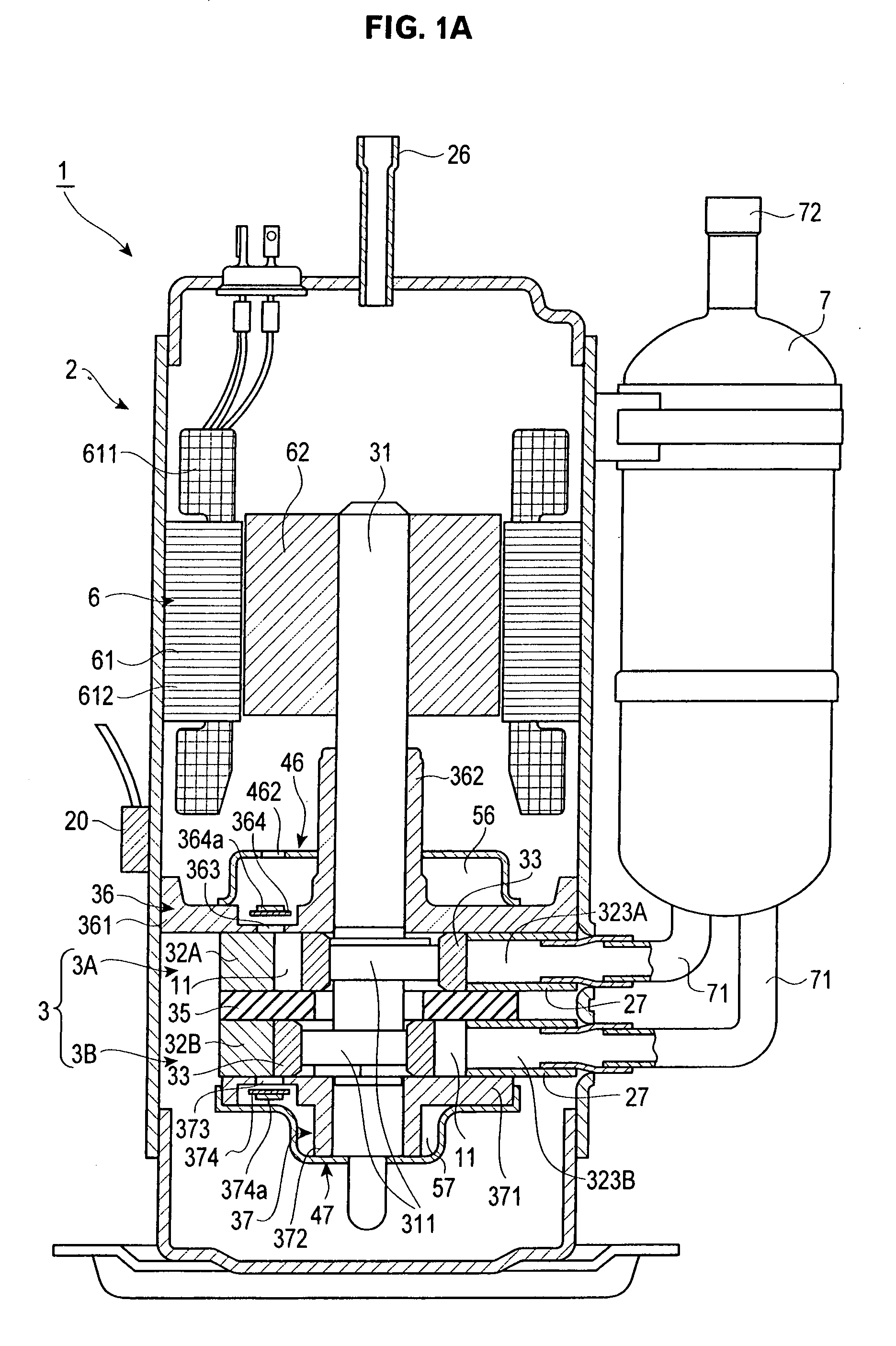
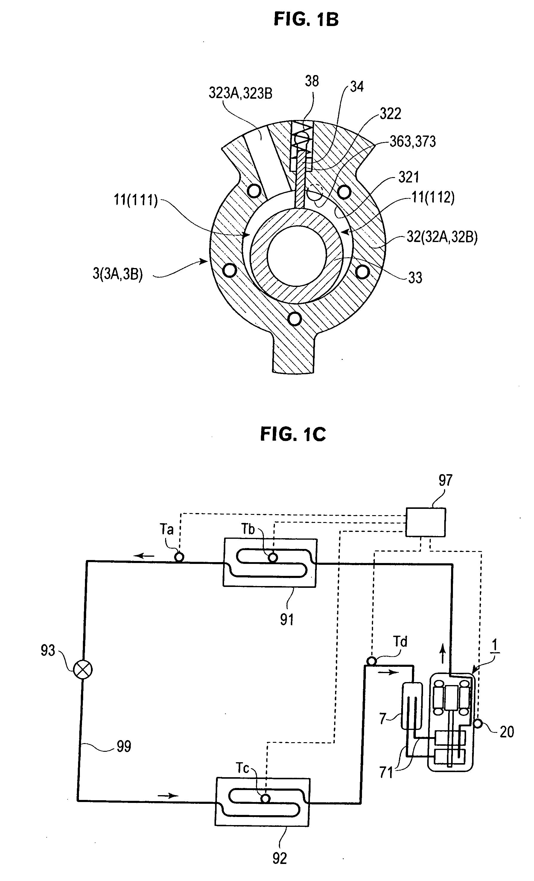
[0082]Next, a third embodiment of the present invention is explained with reference to FIGS. 3A and 3B. FIG. 3A is a perspective view of the upper muffler cover of a rotary compressor in accordance with the third embodiment of the present invention, and FIG. 3B is a partial sectional view of a lower part of the rotary compressor in accordance with the third embodiment of the present invention. In FIGS. 3A and 3B, the same reference symbols are applied to elements that are the same as those in FIG. 1A showing the first embodiment, and the detailed explanation thereof is omitted. The refrigeration cycle is...

third embodiment

[0083]As shown in FIG. 3A, in the third embodiment, a cut and raised part 465 capable of being pressed simultaneously with the pressing of the whole of the upper muffler cover is provided in the end plate part 463 of the upper muffler cover 46.

[0084]As shown in FIG. 3B, the cut and raised part 465 is open toward the inner peripheral surface of the closed container 2 as the upper muffler discharge hole 462 so that the refrigerant discharged from the upper muffler chamber 56 is sprayed directly onto the inner peripheral surface of the closed container 2. Further, the discharge temperature sensor 20 is mounted on the outer peripheral surface of the closed container 2 opposed to the sprayed portion.

second embodiment

[0085]Thereby, the upper muffler discharge hole 462 that is open toward the inner surface of the closed container can be formed without separately fabricating the side plate part 464 of the upper muffler cover 46 as compared with the second embodiment, so that the degree of superheat of intake refrigerant can be kept proper with high accuracy at a lower cost.

[0086]Next, a fourth embodiment of the present invention is explained with reference to FIG. 4. FIG. 4 is a partial sectional view of the lower part of a rotary compressor in accordance with the fourth embodiment of the present invention. In FIG. 4, the same reference symbols are applied to elements that are the same as those in FIG. 1A showing the first embodiment, and the detailed explanation thereof is omitted. The refrigeration cycle is the same as that in the first embodiment shown in FIG. 1C.


PUM


Abstract

A problem to be solved by the present invention is that the temperature of a refrigerant discharged from a compression section can be detected more exactly without being influenced by variable factors existing around the compression section. In a rotary compressor 1 having a motor 6 and a compression section 3 provided in a closed container 2, and also having a discharge pipe 26 provided in an upper part of the closed container 2 to discharge a refrigerant compressed by the compression section 3 to the outside of the closed container 2, a refrigerant discharge part 462 for discharging the refrigerant compressed by the compression section 3 toward the inner peripheral surface of the closed container 2 is provided, and a discharge temperature sensor 20 for detecting the discharge temperature of compressed refrigerant is arranged in a portion opposed to the refrigerant discharge part 462 on the outer peripheral surface side of the closed container 2.

Description

TECHNICAL FIELD[0001]The present invention relates to a rotary compressor used for air conditioners and water heaters. More particularly, it relates to a technique used to control the capacity of a heat pump system and to ensure the reliability of a compressor by exactly detecting the discharge temperature of a refrigerant compressed by a compression section.BACKGROUND ART[0002]The compressor used for the refrigeration cycle of a heat pump system has a problem in that if the degree of superheat of the intake refrigerant thereof is too high, the density of intake refrigerant decreases, so that the capacity and efficiency of compressor decreases, and a problem in that the temperature of the whole of the compressor rises, so that the reliability of compressor, especially the durability of motor winding and insulating paper, decreases.[0003]On the other hand, if the intake refrigerant is not in a superheated state but in a wet state, that is, in a state in which the ratio of liquid is h...

Claims


Application Information

Patent Timeline
Patent Type & Authority Applications(United States)
IPC IPC(8): F25B49/02F25B13/00F25D19/00
CPCF04C18/3564Y02B30/741F04C23/008F04C29/042F04C2270/19F25B1/04F25B49/02F25B2400/13F25B2400/23F25B2600/0253F25B2600/21F25B2600/2509F25B2600/2513F25B2700/21152F25D29/005F04C23/001Y02B30/70
Inventor MORISHITA, TAKUMOROZUMI, NAOYAUEDA, KENSHI
Owner FUJITSU GENERAL LTD
Why Eureka
Try Eureka