Self-contained electrostatic air/oil separator for aircraft engine

a technology of air/oil separator and aircraft engine, which is applied in the direction of external electric electrostatic separator, filter regeneration, dispersed particle filtration, etc., can solve the problems of noxious and unpleasant contaminates, oil contamination, and fouling of engine parts

Inactive Publication Date: 2008-04-03
PRATT & WHITNEY CANADA CORP
View PDF28 Cites 24 Cited by
  • Summary
  • Abstract
  • Description
  • Claims
  • Application Information

AI Technical Summary

Problems solved by technology

For example, the compressed air streams used in gas turbine engines to pressurize labyrinth seals for the engine main bearings in order to avoid excessive loss of lubricating oil, invariably become contaminated with oil in the form of particles suspended in the air.
Loss of contaminated air from the labyrinth seals in the compressor disadvantageously causes fouling of the engine parts and produces noxious and unpleasant contaminates in air drawn from the compressor for cabin pressurization.
The increased loss of lubricating oil from the engine oil tank further disadvantageously necessitates larger capacity oil tanks, thereby adding to the overall weight of the engine, which is particularly a problem relating to aircraft engines.

Method used


Image

  • Self-contained electrostatic air/oil separator for aircraft engine
  • Self-contained electrostatic air/oil separator for aircraft engine

Examples


Embodiment Construction

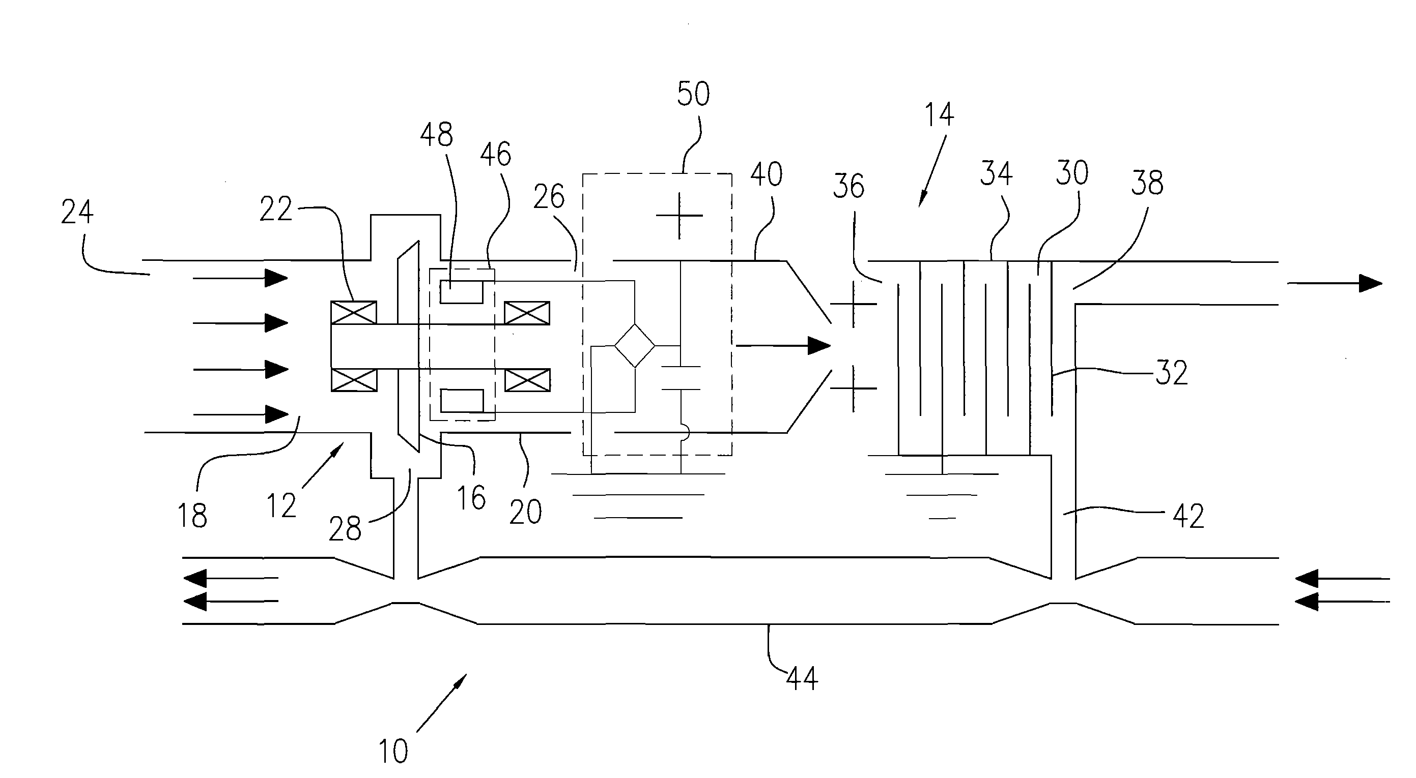
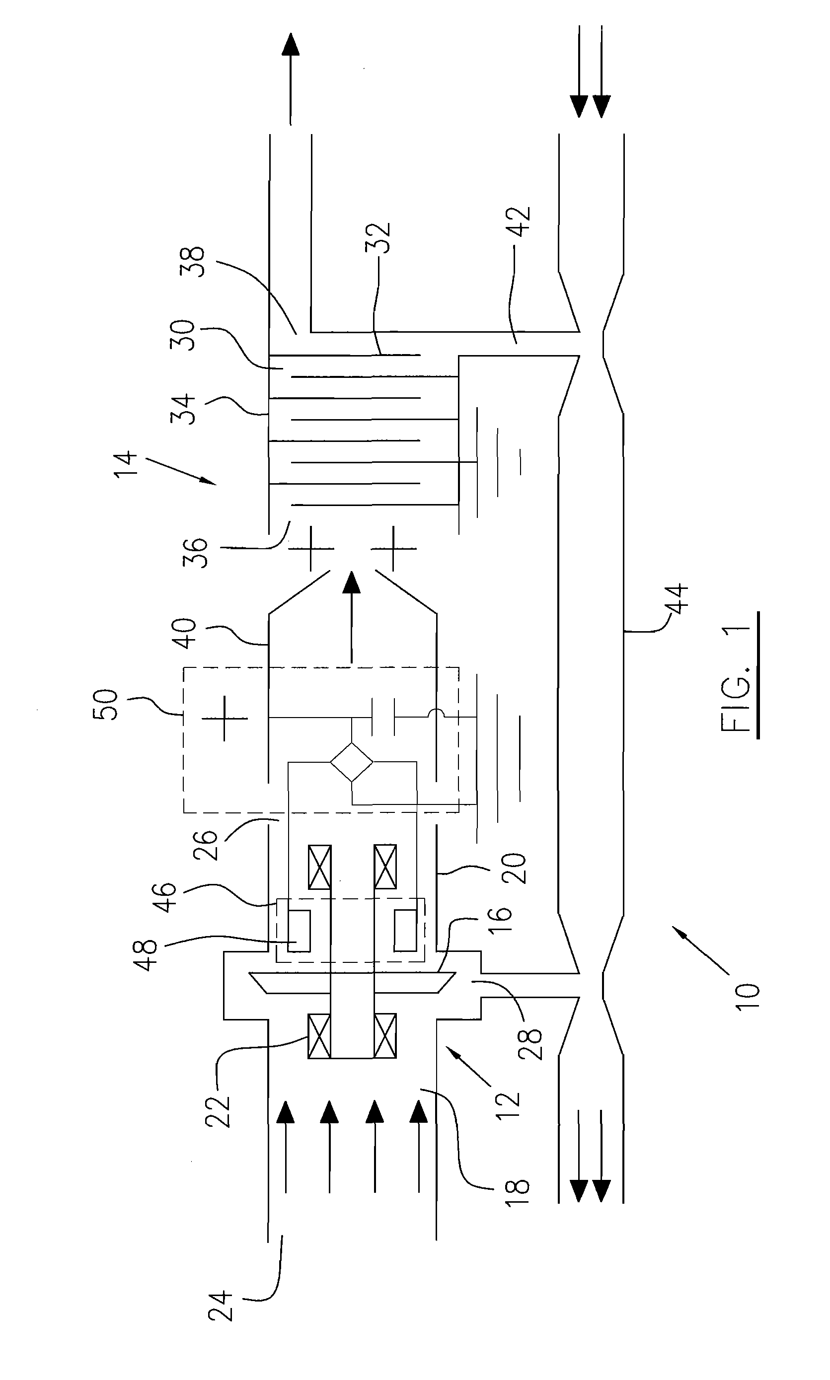
[0012]Referring to FIG. 1, an air / oil separator generally indicated by numeral 10 includes a centrifugal separation stage 12 in fluid communication with a downstream electrostatic separation stage 14. The centrifugal separation stage 12 includes a turbine rotor 16 disposed in a passage 18, for example a casing 20. The turbine rotor, for example having a plurality of blades mounted on a rotor shaft (not indicated), is supported through a pair of bearings 22 on a stationary structure (not shown) within the casing 20 and is thereby adapted to be rotated by a fluid flow passing through the passage 18 from an inlet end 24 to an outlet end 26 of the passage 18. The casing 20 preferably includes a first oil drainage outlet 28 located in a lower portion of the passage 18.

[0013]The electrostatic separation stage 14 preferably includes a labyrinth path 30 which is preferably formed by a plurality of electrically conductive walls 32 mounted transversely within a casing 34 with respect to a flu...


PUM

PropertyMeasurementUnit
DC voltageaaaaaaaaaa
polarityaaaaaaaaaa
electrically conductiveaaaaaaaaaa

Abstract

An air / oil separator for use in a gas turbine engine comprises a centrifugal separation stage in fluid communication with a downstream electrostatic separation stage. The centrifugal separation stage rotationally drives an electric generator to power the electrostatic separation stage.

Description

TECHNICAL FIELD[0001]The invention relates generally to an apparatus for separating a liquid in suspension, and more particularly, to an improved air / oil separator for use in a gas turbine engine.BACKGROUND OF THE ART[0002]Gas turbine engine oil systems require a separator for separating air and oil from the air / oil mixture produced during engine operation. These mixtures vary from oil emulsified with air, to air contaminated by droplets of oil. For example, the compressed air streams used in gas turbine engines to pressurize labyrinth seals for the engine main bearings in order to avoid excessive loss of lubricating oil, invariably become contaminated with oil in the form of particles suspended in the air. Loss of contaminated air from the labyrinth seals in the compressor disadvantageously causes fouling of the engine parts and produces noxious and unpleasant contaminates in air drawn from the compressor for cabin pressurization. Engine oil tanks, auxiliary gearboxes, and the oil ...

Claims


Application Information

Patent Timeline
Patent Type & Authority Applications(United States)
IPC IPC(8): B03C3/011
CPCB03C9/00
Inventor DAUKANT, ROBERT ALLAN
Owner PRATT & WHITNEY CANADA CORP
Why Eureka
Try Eureka