Kneader

a kneading machine and kneading technology, which is applied in the field of kneading machines, can solve the problems of increasing the space for the installation increasing the size of the bottom portion of the kneading machine, etc., and achieves the effect of increasing the volume of the space where papermaking materials are processed, and increasing the kneading

a kneading machine and kneading technology, which is applied in the field of kneading machines, can solve the problems of increasing the space for the installation increasing the size of the bottom portion of the kneading machine, etc., and achieves the effect of increasing the volume of the space where papermaking materials are processed, and increasing the kneading

US20080078853A1Inactive Publication Date: 2008-04-03NIPPON PAPER IND CO LTD +1

Image

  • Kneader
  • Kneader
  • Kneader

Examples


Embodiment Construction

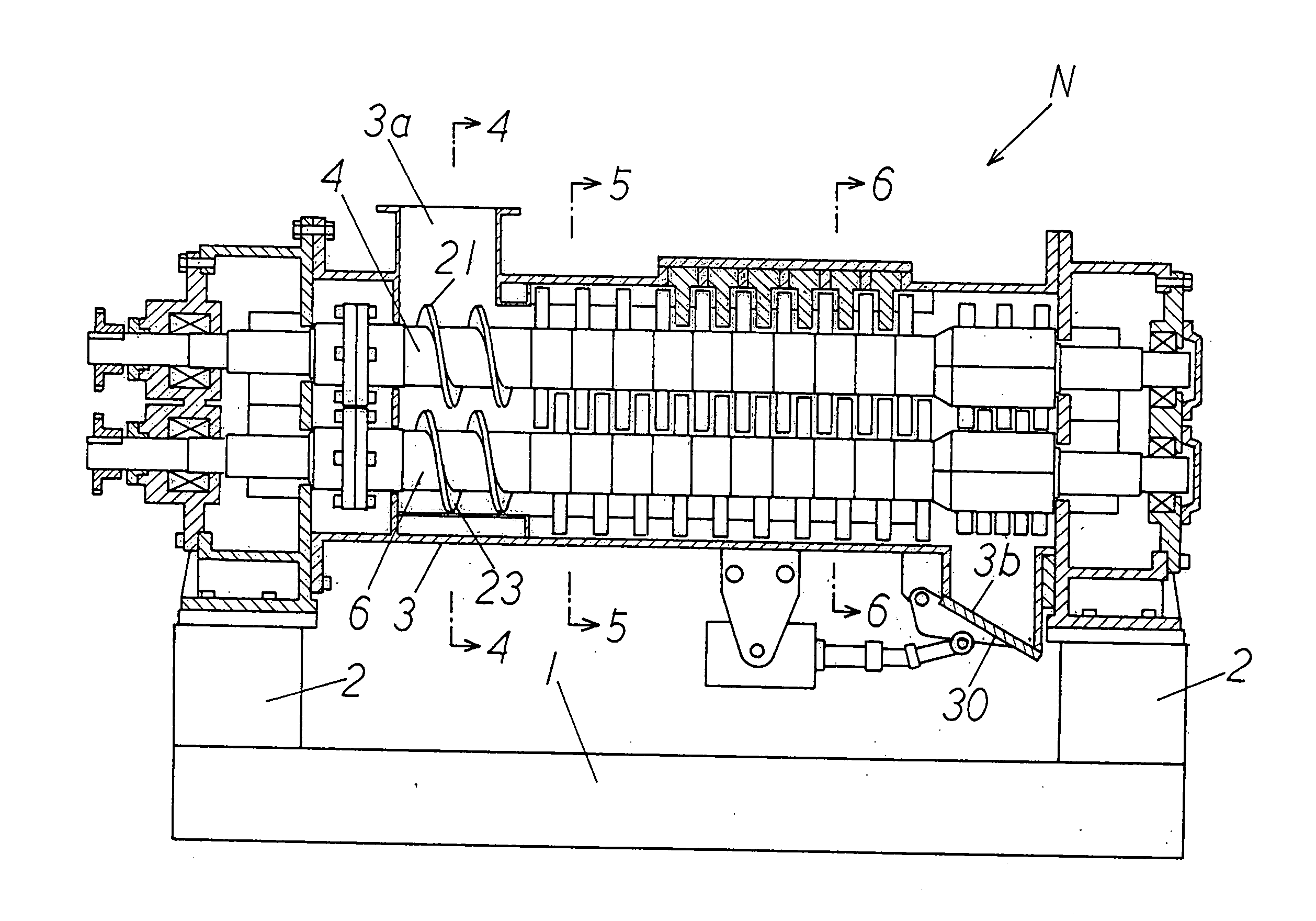
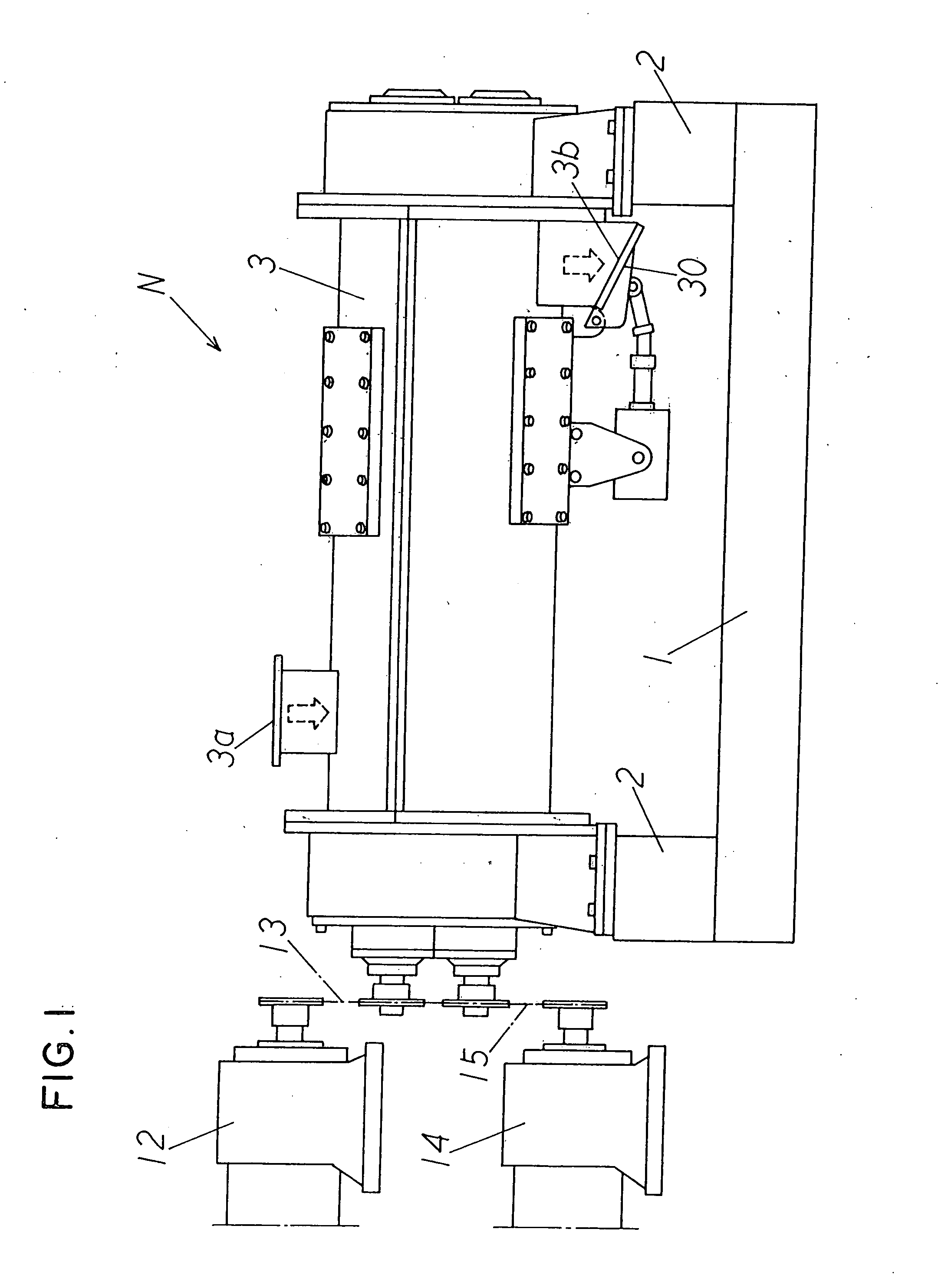
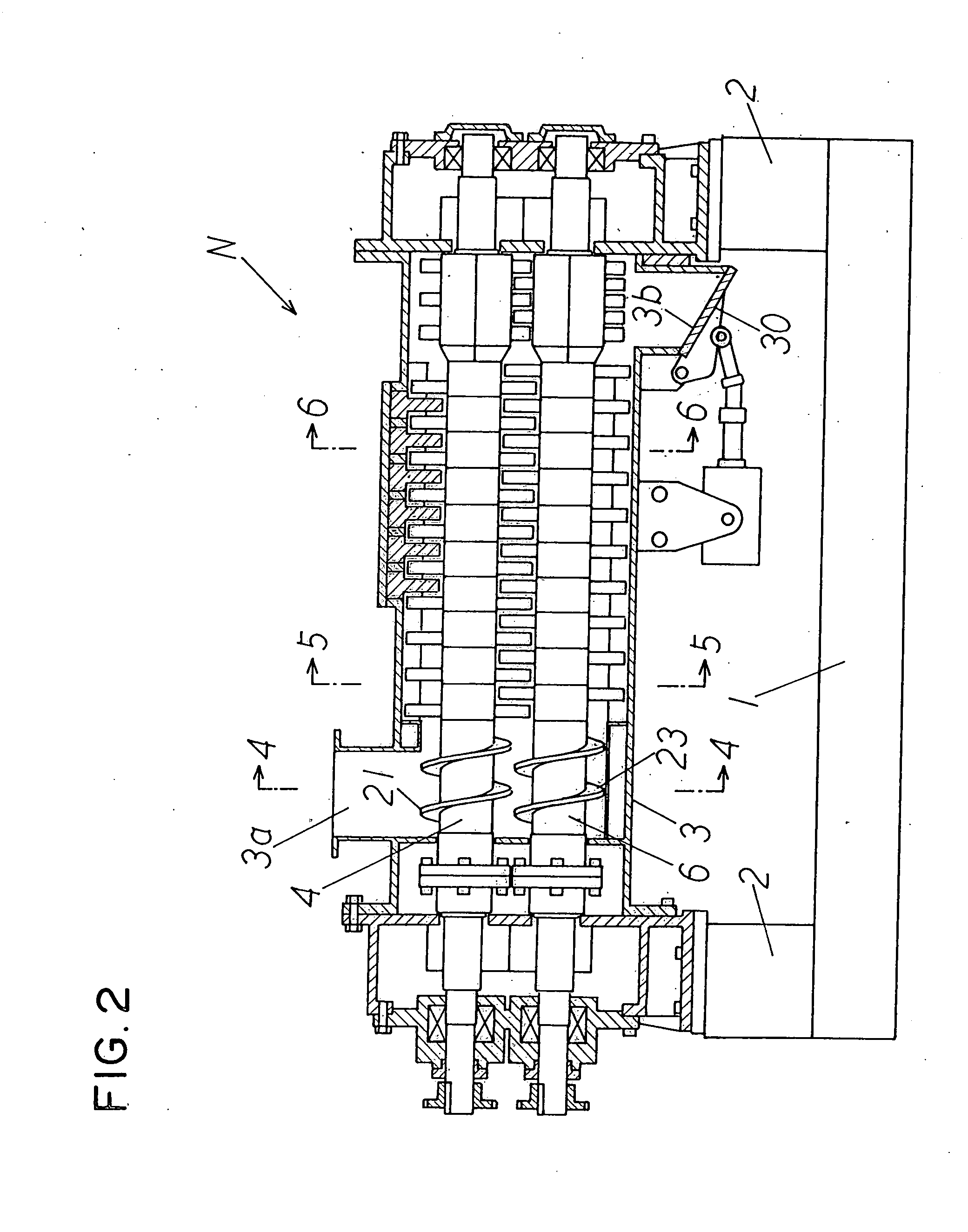
[0022]Hereunder, embodiments of a kneader of the invention will be explained with reference to the accompanying drawings. In FIGS. 1-8, the reference alphabet N represents a kneader, and the kneader N is used for kneading papermaking materials such as, for example, used paper and waste sheets. Specifically, the kneader N kneads them in such a way that ink materials (undispersive ink such as UV and toner) which are mixed into a recycled pulp are separated from the pulp, and a casing 3 is supported on a base 1 through supporting members 2.

[0023]The casing 3 includes a papermaking material supply opening 3a and a papermaking material outlet 3b which is located lower than the papermaking material supply opening 3a. Inside the casing 3, as shown in FIGS. 4-6, first, second, third and fourth rotational shafts 4, 5, 6, 7 are provided. First, second, third and fourth blades 8, 9, 10, 11 for kneading are respectively provided on the first, second, third and fourth rotational shafts 4, 5, 6, ...


PUM

PropertyMeasurementUnit
heightaaaaaaaaaa
lengthaaaaaaaaaa
heightsaaaaaaaaaa

Abstract

A kneader includes a casing with a papermaking material supply opening and a papermaking material outlet located below the papermaking material supply opening; at least first, second, third and fourth rotational shafts provided inside the casing; first blades attached to the first rotational shaft; second blades attached to the second rotational shaft; third blades attached to the third rotational shaft; and fourth blades attached to the fourth rotational shaft. The first rotational shaft and the second rotational shaft are located at the same height and are arranged parallel to each other, and the third rotational shaft and the fourth rotational shaft are located at the same height and are arranged parallel to each other. The third rotational shaft is located under the first rotational shaft and the fourth rotational shaft is located under the second rotational shaft, respectively.

Description

BACKGROUND OF THE INVENTION AND RELATED ART STATEMENT [0001]The invention relates to a kneader, especially, a kneader which increases a kneading effect.[0002]Conventionally, kneaders, such as those shown in FIG. 2 in Japanese. Utility Model Publication No. 60-156198, comprise two shafts respectively including blades in a casing with a papermaking material supply opening and a papermaking material outlet.[0003]In the above-mentioned kneader, used paper is kneaded at the portion wherein the blades which are respectively provided in the two shafts intersect. In order to increase the kneading effect of the used paper by the kneader, the two shafts are respectively required to be made longer in a longitudinal direction. However, with the increase of the length of the shafts in a longitudinal direction, a size of the bottom portion of the kneader increases, and a space for the installation of the bottom portion of the kneader also increases.[0004]An object of this invention is to provide ...

Claims


Application Information

Patent Timeline
03 Apr 2008
Publication
US20080078853A1
IPC
B02C18/06
CPC
B01F7/00133; B01F7/00158; B01F7/00258; B01F7/00641; B01F7/00975; B01F7/042; D21D1/38; B01F15/00785
Inventors
SUGINO, MITSUHIRO; ONIZAKI, TAKASHI