

Position-sensor-free control method for transformer substation patrol robot
A sensor control and robot technology, applied in the direction of motor generator control, electronic commutation motor control, control system, etc., can solve the problem of increasing system hardware cost and maintenance cost, increasing the space size and volume of the motor, reducing power density, etc. problem, to increase hardware cost and maintenance cost, increase space size and volume, and reduce power density
- Summary
- Abstract
- Description
- Claims
- Application Information
AI Technical Summary
Problems solved by technology
Method used
Image

Examples
Embodiment Construction
[0018] The present invention will be further described below in conjunction with the accompanying drawings.
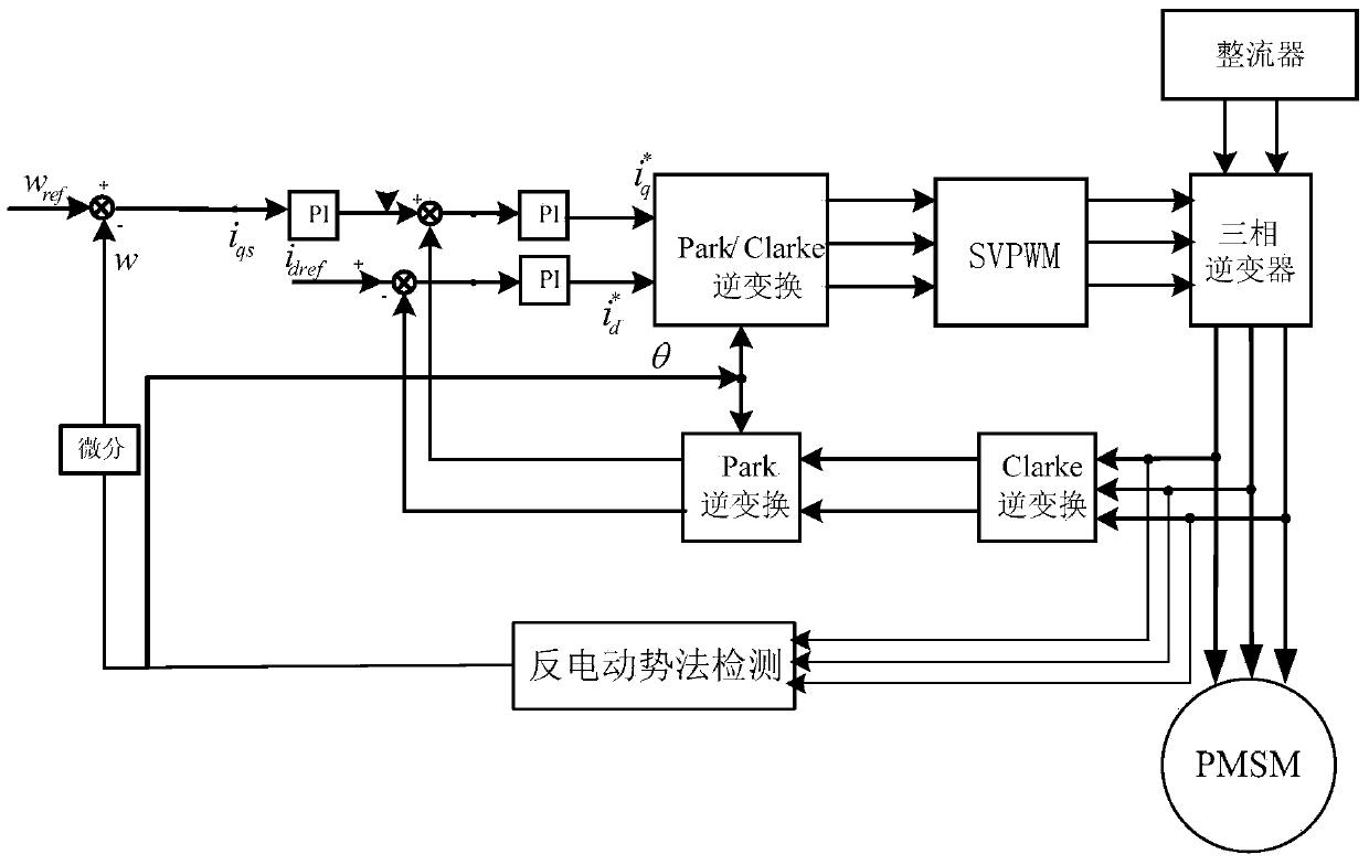
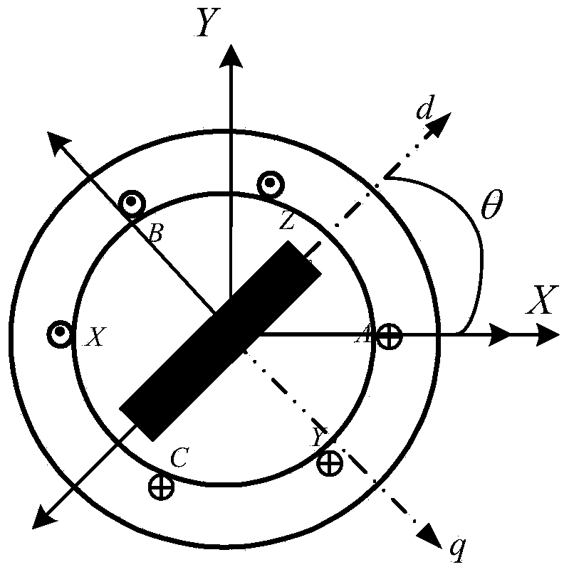
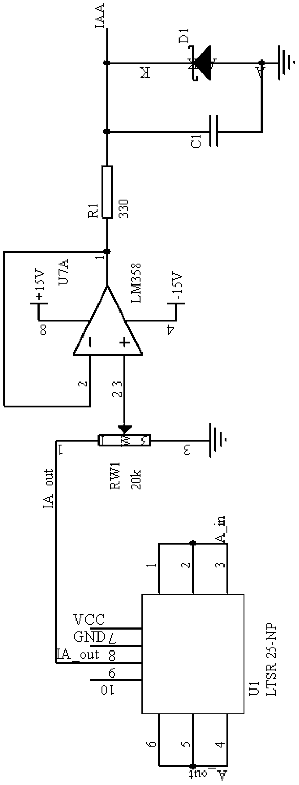
[0019] A position-sensing control method for a substation inspection robot. Before the robot starts, two voltage pulses are applied to the motor, and the action time of the two voltage pulses is T 1 and T 2 , at this stage, it is required that the robot cannot shake due to the injection of voltage pulses, so T 1 ,T 2 are smaller than the motor time constant; use the current sensor to detect T 1 and T 2 The corresponding current change rate △i of the motor in the X-Y axis coordinate system at any time x1 / T 1 、△i y1 / T 1 、△i x1 / T 2 and Δi y1 / T 2 , followed by these four rates of change and the known voltage vector L 11 , L 12 , L 21 and L 22 , the inductance value that forms a function relationship with the rotor position is obtained through calculation, and finally the initial position angle is preliminarily deduced according to the inductance value. ...
PUM
 Abstract
Description
Claims
Application Information