
Deployable heat shield and deceleration structure for spacecraft

a technology for spacecraft and thermal protection, applied in the direction of cosmonautic thermal protection, cosmonautic vehicles, systems for re-entry to earth, etc., can solve the problems of too risky for astronauts or useful payloads, and achieve the effect of sure and reliable function

Inactive Publication Date: 2008-04-03
AIRBUS DEFENCE & SPACE
View PDF10 Cites 47 Cited by
  • Summary
  • Abstract
  • Description
  • Claims
  • Application Information

AI Technical Summary

Benefits of technology

[0009]The apparatus according to the invention further has several technical advantages. For example, the relatively low mass of the inventive apparatus achieves a weight reduction of about 50% relative to the known heat shield and deceleration apparatuses for spacecraft, especially relative to foldable structures with an ablation arrangement or relative to inflatable foldable chamber systems with such an ablation arrangement. Due to this weight reduction, even relatively small payload carriers or launch vehicles can receive and carry an apparatus comprising a folded system according to the invention. Also due to the weight savings achieved through use of the foldable structure according to the invention, a larger or heavier total useful payload can be received and carried in the vehicle and therefore be transported in a more economical manner. The inventive apparatus also makes it possible to utilize small space capsules, which otherwise would quickly become too hot without a large heat shield and would therefore be too risky for use by astronauts or useful payloads. Furthermore, the inventive apparatus, in addition to the braking or decelerating effect, can also provide a flight path stabilizing function for the spacecraft as it enters and flies through the atmosphere.
[0010]Thus, the apparatus according to the invention combines several very different functions. It ensures a secure and reliable unfolding deployment of the individual heat shield panels to form a self-stiffening aerodynamic braking shield or parachute-like structure that can surely take-up the arising high deceleration loads. Also, the individual shield panels respectively comprise heat resistant material that does not melt, vaporize, burn-up or degrade during the frictional braking in the atmosphere. Thus, the inventive apparatus does not cause pollution of the atmosphere due to thermal ablation of the heat shield material during entry into the atmosphere, as this can be the case with conventional heat shield systems. Furthermore, the inventive apparatus has an extremely light weight and stiff structure, so that the useful payload of the spacecraft can be as large and as heavy as possible.
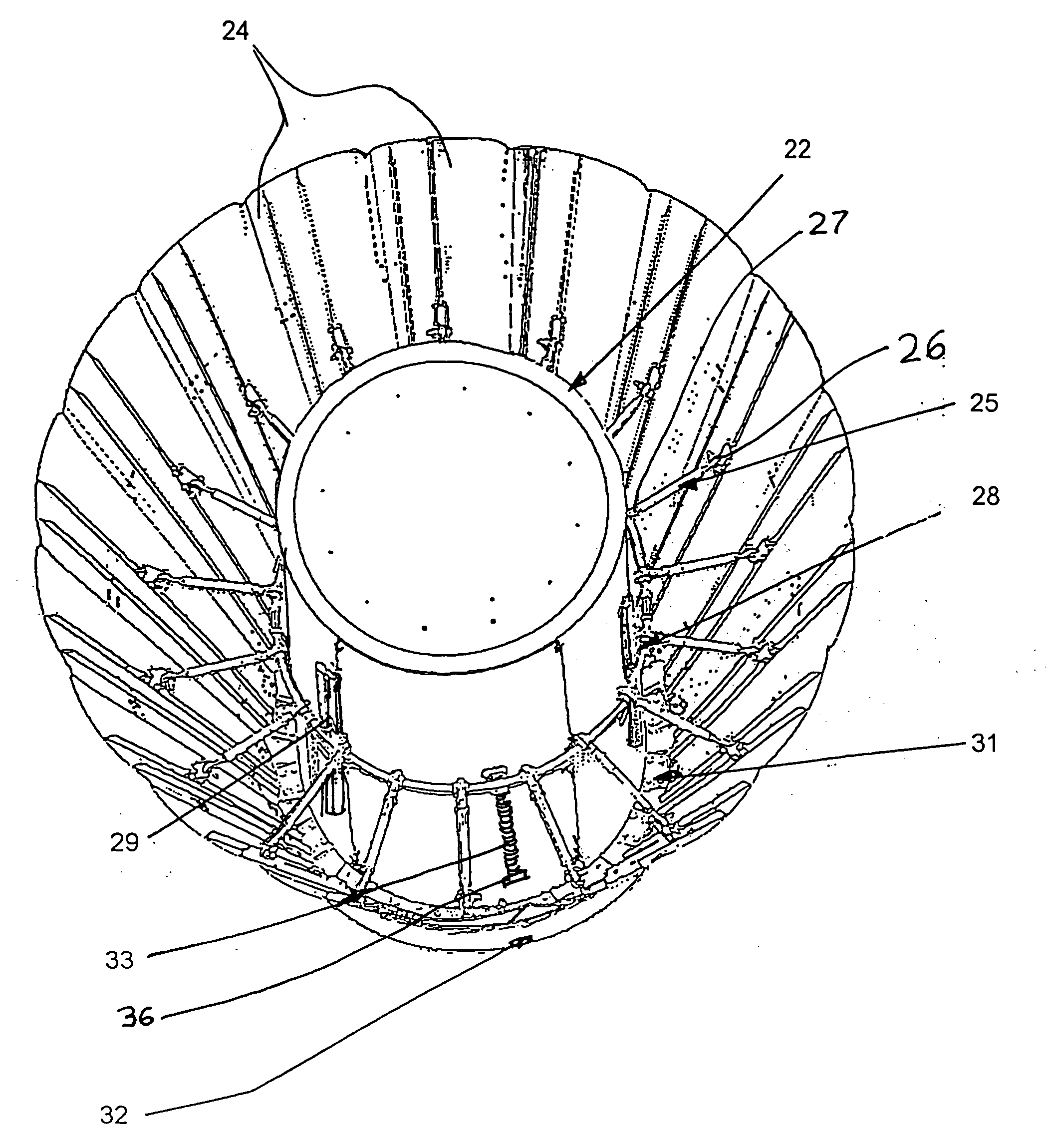
[0012]The unfolding or deployment and locking mechanism of the apparatus according to the invention is constructed in such a stiff and robust manner so that it still functions surely and reliably even in the event of a deformation of the reinforcing structure do to thermally induced tensions in the structure in orbit, for example on the sun-exposed side of the spacecraft relative to the shadow side thereof, and also so that the unfolding and locking mechanism does not fail under the very high thermal and mechanical loads during entry into the earth's atmosphere or into the atmosphere of a different heavenly body, by which temperatures up to 1700° C. can arise.

Problems solved by technology

The inventive apparatus also makes it possible to utilize small space capsules, which otherwise would quickly become too hot without a large heat shield and would therefore be too risky for use by astronauts or useful payloads.
Furthermore, the inventive apparatus has an extremely light weight and stiff structure, so that the useful payload of the spacecraft can be as large and as heavy as possible.

Method used


Image

  • Deployable heat shield and deceleration structure for spacecraft
  • Deployable heat shield and deceleration structure for spacecraft
  • Deployable heat shield and deceleration structure for spacecraft

Examples


Embodiment Construction

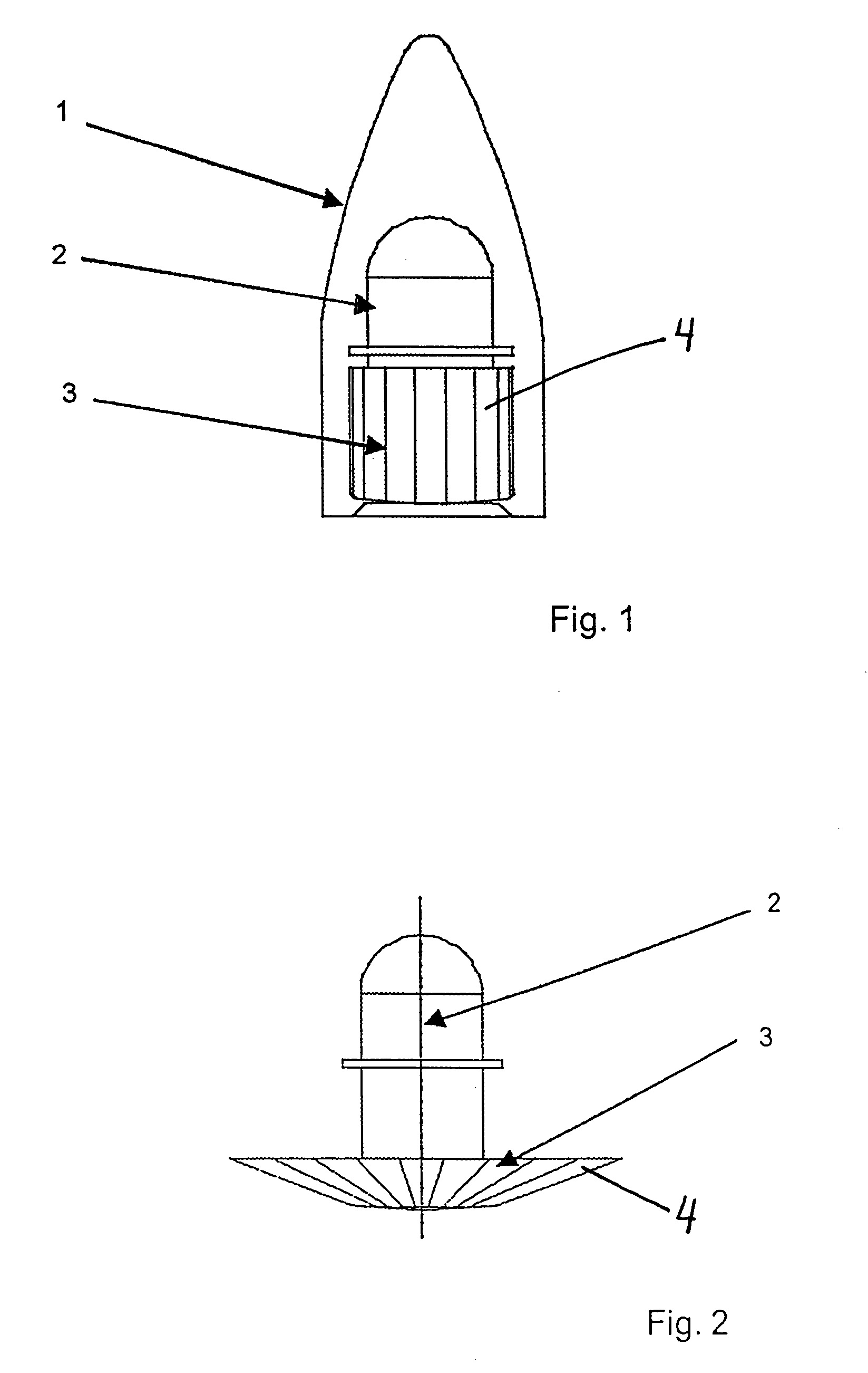
[0027]FIG. 1 shows the nose cone portion of a launch rocket 1 carrying a useful payload 2 in the form of a spacecraft and particularly a reentry vehicle 2. The reentry vehicle 2 is outfitted or equipped with a foldable deployable heat shield arrangement 3 on the portion of the reentry vehicle 2 that faces forward in the flight direction during entry of the vehicle 2 into a planet's or moon's atmosphere. The heat shield arrangement 3 is stowed in a folded condition in the interior of the nose cone of the rocket 1.

[0028]FIG. 2 shows the reentry vehicle 2 after its release outside of the rocket 1, whereby the heat shield arrangement 3 has been unfolded, deployed and extended into a configuration to carry out its heat shielding and decelerating functions as the reentry vehicle 2 enters into the earth's atmosphere or the atmosphere of a different heavenly body. The heat shield arrangement comprises a plurality of individual panels 4 that are movably mounted on the structure of the reentr...


PUM


Abstract

An apparatus for heat shielding and deceleration of a spacecraft comprises an unfoldable shield of individual panels made of a high temperature resistant fiber reinforced ceramic and pivotally mounted on the outer structure of the spacecraft. An unfolding ring slides axially along the body of the spacecraft. The panels are pivotally connected to the unfolding ring by compression struts acting as toggle levers. Tension springs pull the unfolding ring axially along the spacecraft body to toggle out the compression struts so as to outwardly pivotally deploy the panels. The unfoldable shield can be arranged on the forward end or the rear end of the spacecraft relative to its flight direction upon entry into the atmosphere.

Description

PRIORITY CLAIM[0001]This application is based on and claims the priority under 35 U.S.C. §119 of German Patent Application 10 2006 046 572.5, filed on Sep. 30, 2006, the entire disclosure of which is incorporated herein by reference.FIELD OF THE INVENTION[0002]The invention relates to an apparatus for thermal protection and deceleration of spacecraft upon entry of the spacecraft into an atmosphere. The spacecraft can be any type of space vehicle or flying body that is to enter or reenter the atmosphere of the earth or another planet or a planetary moon at a high speed, for which thermal protection and deceleration of the spacecraft are needed.BACKGROUND INFORMATION[0003]Upon entry of spacecraft into the atmosphere of the earth or other planets or planetary moons, heat shields and / or deceleration structures are needed for decelerating the spacecraft and protecting it from excessive heat due to the arising frictional heating as the spacecraft passes through the atmosphere. New spacecr...

Claims


Application Information

Patent Timeline
IPC IPC(8): B64G1/58
CPCB64G1/62B64G1/58B64G1/623
Inventor TRABANDT, ULRICHSCHMID, MANFRED
Owner AIRBUS DEFENCE & SPACE
Learn More