Method and apparatus for forming hollow moldings having thin film on inner surface

a hollow molding and inner surface technology, applied in the field of hollow moldings having thin films on their inner surfaces, can solve the problems of high cost, failure of deposited quality, and high care of body parts, and achieve the effect of excellent deposited quality and inexpensive formation

Inactive Publication Date: 2008-04-03
JAPAN STEEL WORKS LTD
View PDF3 Cites 17 Cited by
  • Summary
  • Abstract
  • Description
  • Claims
  • Application Information

AI Technical Summary

Benefits of technology

[0016]Thus, according to the invention, the inner surface of at least one of the paired semi-hollow bodies formed of the stationary mold and the movable mold is deposited in the mold while being left in the stationary mold or the movable mold, by covering it with a deposition chamber having a deposition element such as a target electrode, a substrate electrode or a vacuum suction pipe therein. Specifically, the semi-hollow bodies are not taken out from the mold but are deposited in the mold by using the depositing chamber, so that the deposited face is not soiled on its surface with hand or dust. According to the invention, therefore, it is possible as a special effect to provide a hollow molding of an excellent deposited quality having the thin film on its inner surface. Moreover, the deposition is performed in the mold while the semi-hollow bodies are left in the mold, so that the semi-hollow bodies need no storage management. Merely by preparing a deposition apparatus, moreover, there is attained another advantage that the automatic molding can be inexpensively formed without employing any special mold.

Problems solved by technology

When the hollow molding having the thin film on its inner surface is to be formed by the method of the related art, there arise many problems because the body portion has to be formed in advance by the injection molding method and has to be transferred into the vacuum tank for the deposition.
Therefore, the body portion may be soiled on its surface with hand or dust while being stored, so that it may cause a deposition failure.
In order to avoid this, the handling of the body portion requires the highest care and raises the cost.
On the other hand, the prefabricated body portion is once stored so that its storage raises a management problem.
In addition, the body portion has to be once extracted from the mold before it is deposited, and has to be again mounted in the mold before it is jointed, thus lowering the productivity.
The molding methods of the related art, however, cannot form the thin film of the order of several microns on the inner surface of the hollow molding.

Method used


Image

  • Method and apparatus for forming hollow moldings having thin film on inner surface
  • Method and apparatus for forming hollow moldings having thin film on inner surface
  • Method and apparatus for forming hollow moldings having thin film on inner surface

Examples


first embodiment

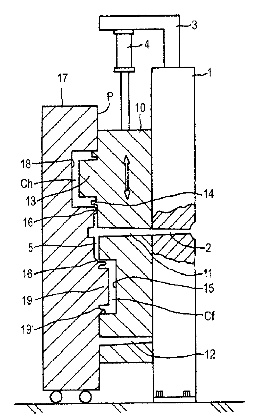
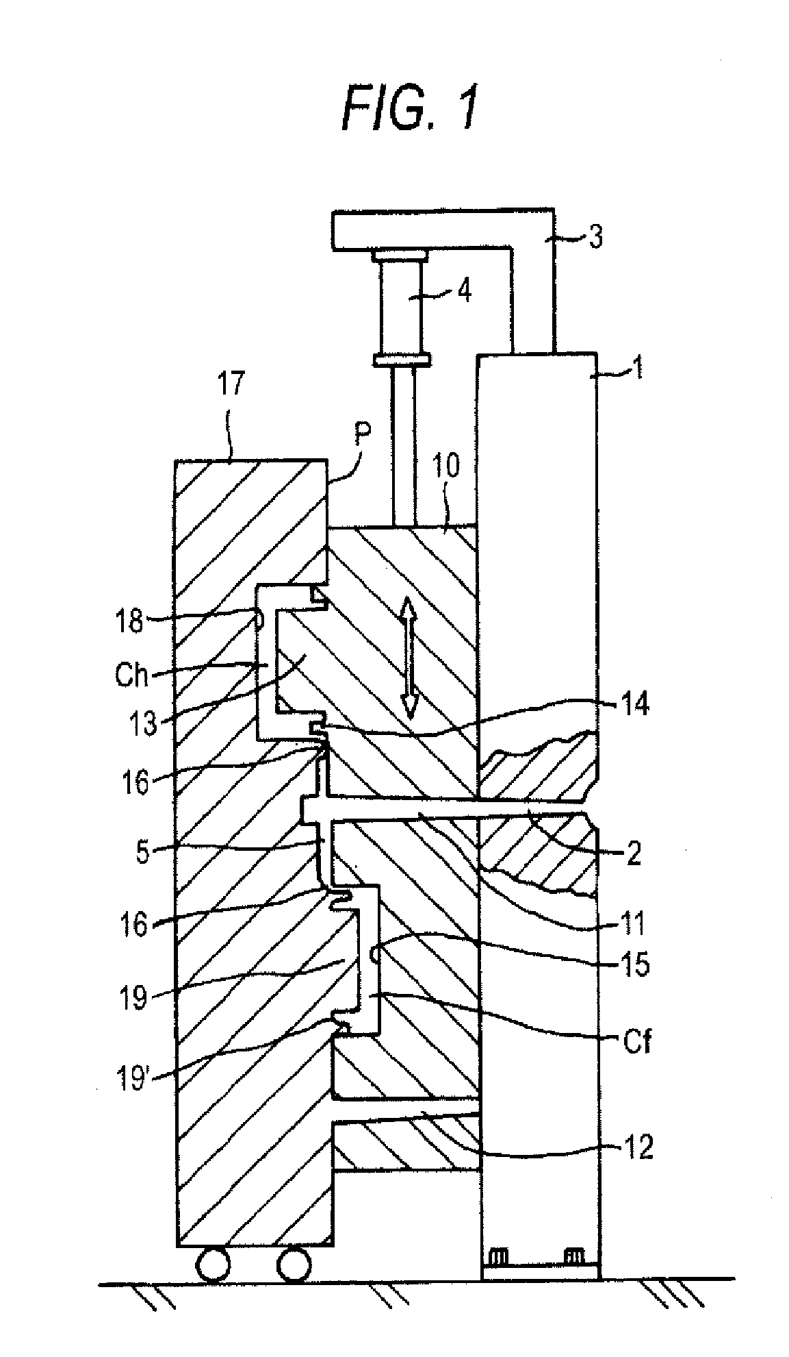
[0022]Here is described a molding example of a hollow molding article having a thin film in its inside, which is formed by injection-molding a cup-shaped body portion having a thin film such as a reflecting film on its inner surface and a thin lens-shaped cover member for sealing the opening of the body portion, by forming the thin film on the inner surface of the body portion in the mold, and by sealing the opening of the body portion with the cover member. An embodiment of the molding apparatus of the invention is described at first. FIG. 1 is a sectional view schematically showing the molding apparatus according to an embodiment of the invention with its mold being closed. as shown in FIG. 1, the molding apparatus includes a stationary mold 1, a slide mold 10 and a movable mold 17. Moreover, the slide mold 10 is so attached to the stationary mold 1 as is driven to slide vertically, as shown in FIG. 1.

[0023]The stationary mold 1 is fixed on the base, as known in the art. In the e...

third embodiment

[0037]FIG. 5 shows a third embodiment, which is composed of a disc-shaped or column-shaped stationary mold 60, and a disc-shaped or column-shaped rotary mold 70. FIG. 5A presents a perspective view showing the stationary mold 60 and FIG. 5B presents a perspective view taken from the side of the parting line face P with its rotary disc 70 being opened. In the parting line face P of the stationary mold 60, as shown, a stationary side recess 61 for forming the body portion is formed at a position radially offset at a predetermined amount from the center position. Moreover, a stationary side core 62 for forming the cover member is formed at a position circumferentially spaced by 120 degrees from that stationary side recess 61. Moreover, a stationary side relief 63 is formed at a position circumferentially spaced by 120 degrees from the stationary side recess 61 or the stationary side core 62. This stationary side relief 63 is formed to have a predetermined depth for receiving the core o...


PUM

PropertyMeasurementUnit
pressureaaaaaaaaaa
shapesaaaaaaaaaa
joint strengthaaaaaaaaaa

Abstract

A movable mold and a slide mold are employed. There is also employed a deposition apparatus which is equipped with a deposition element such as a target electrode in the inside of a depositing chamber. A body portion and a cover member are primarily molded by the movable mold and the slide mold. The molds are opened while the body portion being left in the movable mold and while cover member being left in slide mold. The body portion left in the movable mold is deposited in the molds with its inner surface being covered with the depositing chamber. Next, the slide mold is driven so that the cover member may be registered with the deposited body portion. Then, a secondary molding resin is injected to integrate the body portion and the cover member.

Description

[0001]This application is based on Japanese Patent Application No. 2005-168984, which is incorporated herein by reference.BACKGROUND OF THE INVENTION[0002]1. Field of the Invention[0003]The present invention relates to a method for forming a hollow molding having a thin film on its inner surface, comprising: a primary molding step of injection-molding a pair of semi-hollow bodies by using a stationary mold and a movable mold made movable with respect to the stationary mold, so that its opening may have an abutment portion; a depositing step of forming a thin film on the inner surface of at least one of the semi-hollow bodies formed by the primary molding; and a secondary molding step of integrating the paired semi-hollow bodies to acquire the hollow body, by abutting the opening of the paired semi-hollow bodies deposited, in an upper state where they are left in the molds, and by injecting a molten resin to the abutting portions, a hollow molding obtained by executing the molding me...

Claims


Application Information

Patent Timeline
Patent Type & Authority Applications(United States)
IPC IPC(8): B29C45/16
CPCB29C45/0062B29C45/0408B29C66/54B29C2045/0063Y10T428/1393Y10T428/1321Y10T428/1355Y10T428/1352B29C2045/0067
Inventor NISHIDA, SHOSO
Owner JAPAN STEEL WORKS LTD
Why Eureka
Try Eureka