

Vacuum Deposition Method and Sealed-Type Evaporation Source Apparatus for Vacuum Deposition
- Summary
- Abstract
- Description
- Claims
- Application Information
AI Technical Summary
Benefits of technology
Problems solved by technology
Method used
Image

Examples
embodiment 1
[0080] Currently, when a SiO (an evaporation material) protective film, for example, is deposited on the surface of an eyeglass lens, many lenses are arranged over the upper portion of the vacuum chamber while an open-type evaporation source is disposed on the lower portion thereof. Generally, the protective films are deposited onto the surfaces of lenses by means of the resistance heater. In this case, the deposited lenses are manually replaced with new ones. Moreover, the evaporation material is refilled manually. There are many other works for changing a substrate or an eyeglass lens being a deposition subject substrate and for refilling an evaporation material.
[0081] As SiO (or an evaporation material), there are various materials such as powdered grain particles or tables of several millimeter, precise molded materials called a target, materials of irregular sizes or shapes, and others. These evaporation materials are currently sold on market by manufactures. Other manufacture...
embodiment 2
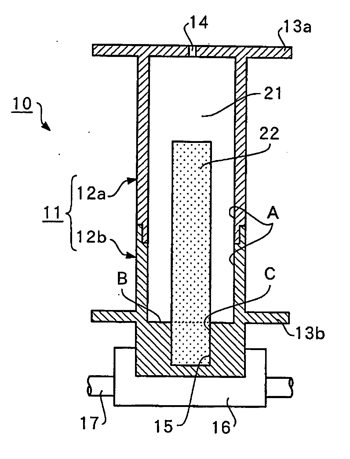
[0102] The second embodiment relates to the vacuum deposition method and the sealed-type evaporation source apparatus corresponding to the vacuum deposition method as shown in FIGS. 5-9. This embodiment can be applied practically to the case where the long lengths of a gas barrier film are continuously produced. Thus, SiO, for example, is deposited by supplying oxygen while SiO is being emitted onto a synthetic resin film, such as polyester film.
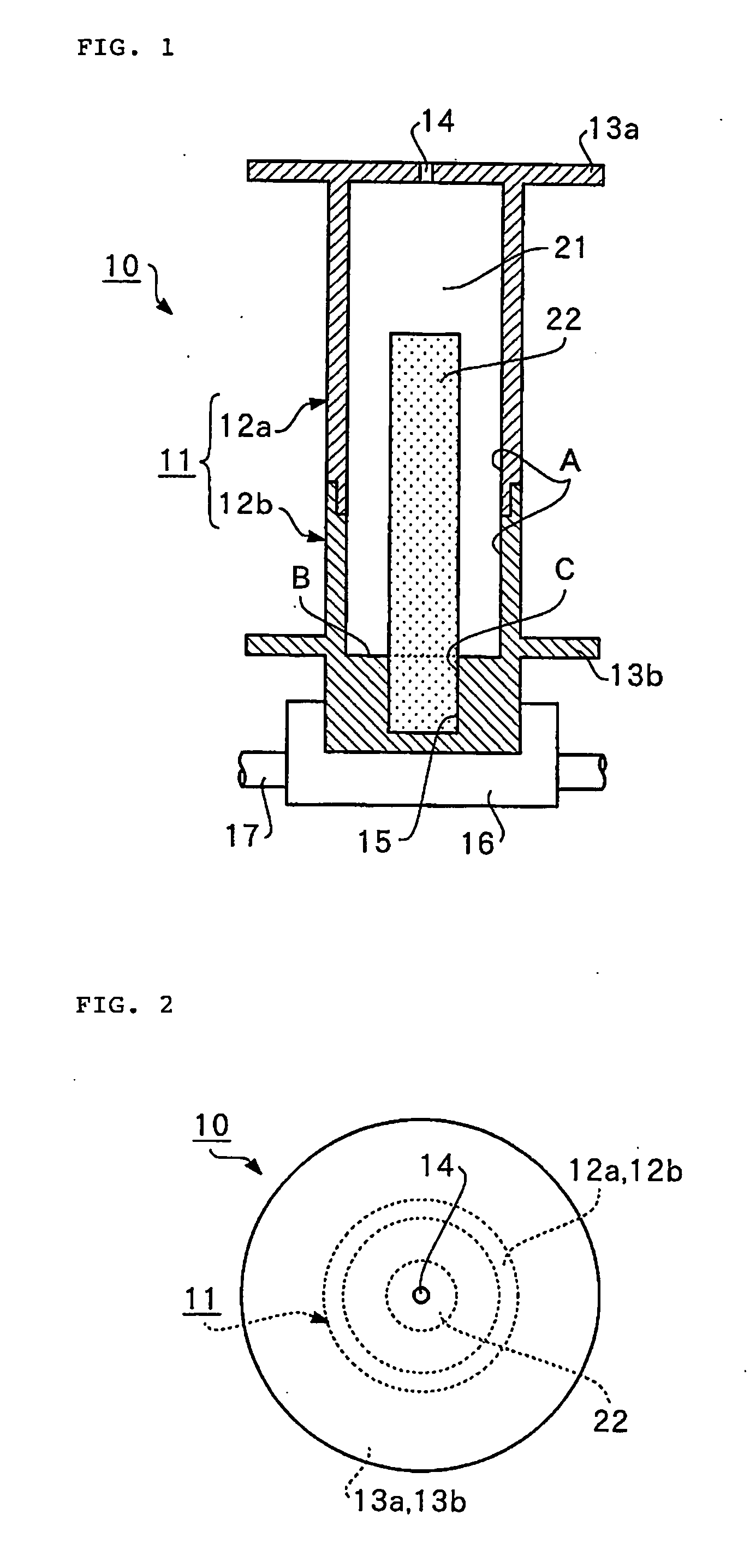
[0103]FIG. 5 is a longitudinal, sectional side view conceptually illustrating the schematic configuration of a sealed-type evaporation source apparatus for vacuum deposition, according to the second embodiment of the present invention. FIG. 6 is a longitudinal, sectional side view conceptually illustrating the aspect after a lapse of a certain time of the operation of the sealed-type evaporation source apparatus in FIG. 5. FIG. 7 is a cross-sectional view schematically illustrating the portion taken along the line 7-7 in FIG. 6.
[0104] In e...
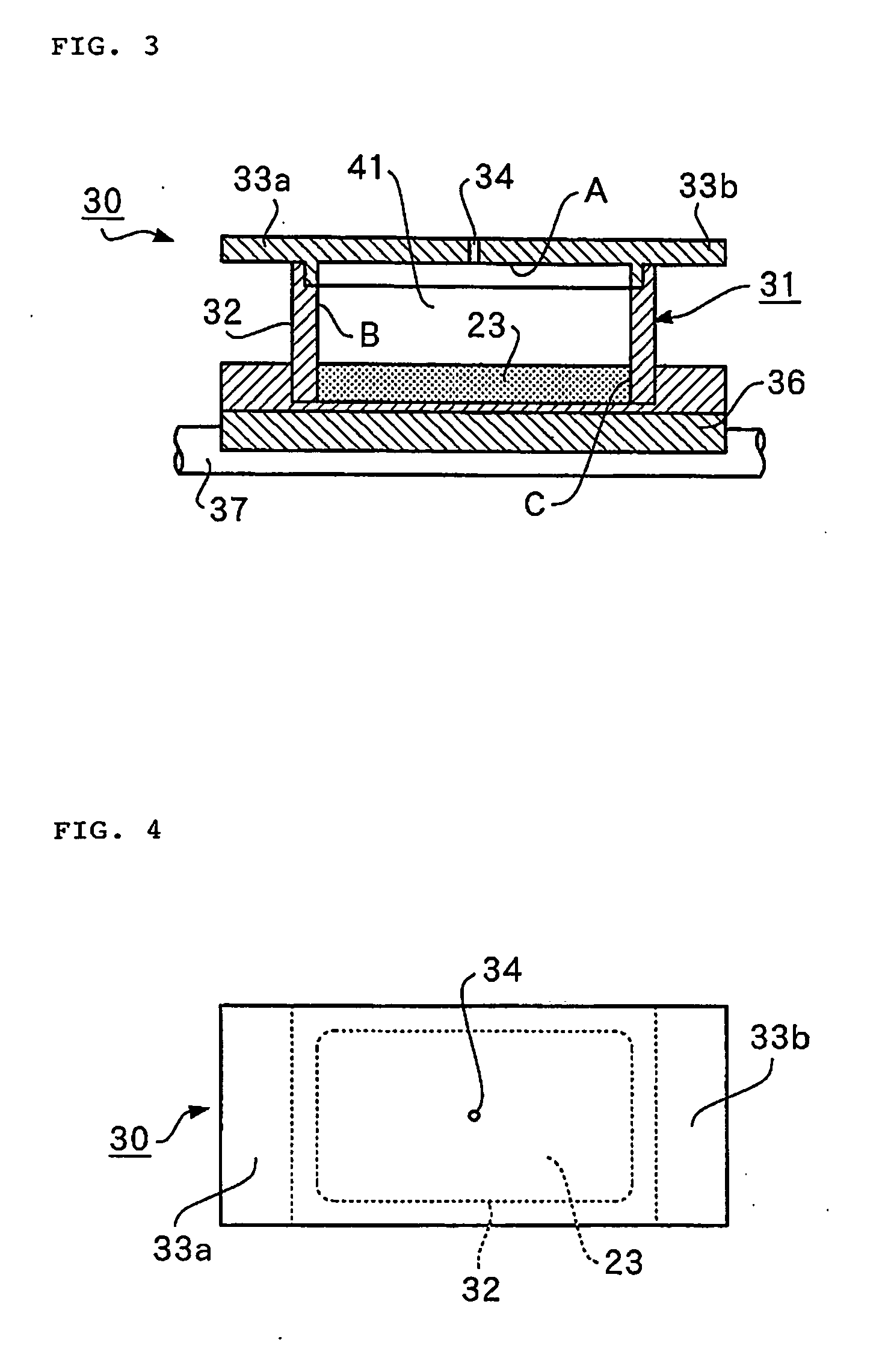
embodiment 3
[0115] The third embodiment corresponds to a variation of the heating the container in the second embodiment.
[0116]FIG. 8 is a longitudinal sectional side view conceptually illustrating the schematic configuration of a sealed-type evaporation source apparatus for vacuum deposition according to the third embodiment. FIG. 9 is a longitudinal sectional view conceptually illustrating a modification of the sealed-type evaporation source apparatus.
[0117] In the sealed-type evaporation source apparatus 70 shown in FIG. 8, the heating container 71 has a straight cylinder, different from the tapered container shown in the second embodiment. The heating container 71 are formed of an upper heating cylinder 72a and a lower heating cylinder 72b, which are vertically dividable. Other constituent elements are identical to those in the embodiment 2. In this case, like numerals are attached to the common constituent elements shown in FIGS. 8 and 9.
[0118] In the sealed type evaporation source of t...
PUM
| Property | Measurement | Unit |
|---|---|---|
| Temperature | aaaaa | aaaaa |
| Area | aaaaa | aaaaa |
| Evaporation enthalpy | aaaaa | aaaaa |
Abstract
Description
Claims
Application Information