
Planar transformer and switching power supply

a technology of switching power supply and planar transformer, which is applied in the direction of electrical apparatus construction details, indirect heat exchangers, cores/yokes, etc., can solve the problems of increasing the switching frequency of dc-dc converters, power supplies accompanies, and increasing the eddy current loss of coils in planar transformers, so as to achieve the effect of cooling primary

Inactive Publication Date: 2008-04-03
TDK CORPARATION
View PDF8 Cites 52 Cited by
  • Summary
  • Abstract
  • Description
  • Claims
  • Application Information

AI Technical Summary

Benefits of technology

[0008]The present invention focuses attention on necessity of an appropriate gap between a primary coil board including a primary coil and a secondary coil board including a secondary coil in order to satisfy conditions of a leakage inductance, a coupling coefficient etc. in planar transformers ...

Problems solved by technology

However, increase of switching frequency in DC-DC converters used for switching power supplies accompanies with increase of eddy current losses of coils in planar transformers.
There is a problem that said structure such as fixing the cooling fin on the magnetic core is less effective to cool down heat generations of coils themselves caused by eddy current losses.
However, in case of planar transformers used for resonation type DC-DC converters in which a wide gap should be provided between primary and secondary coils, it is difficult to keep the wide gap constant when the transfer molding is made.

Method used


Image

  • Planar transformer and switching power supply
  • Planar transformer and switching power supply
  • Planar transformer and switching power supply

Examples


Embodiment Construction

[0025]Referring now to the drawings, an embodiment of the planar transformer and the switching power supply according to the invention is described.

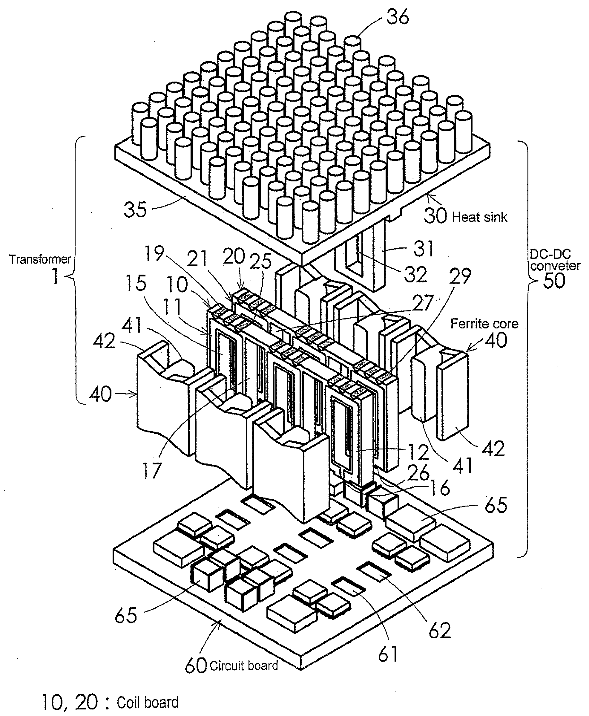
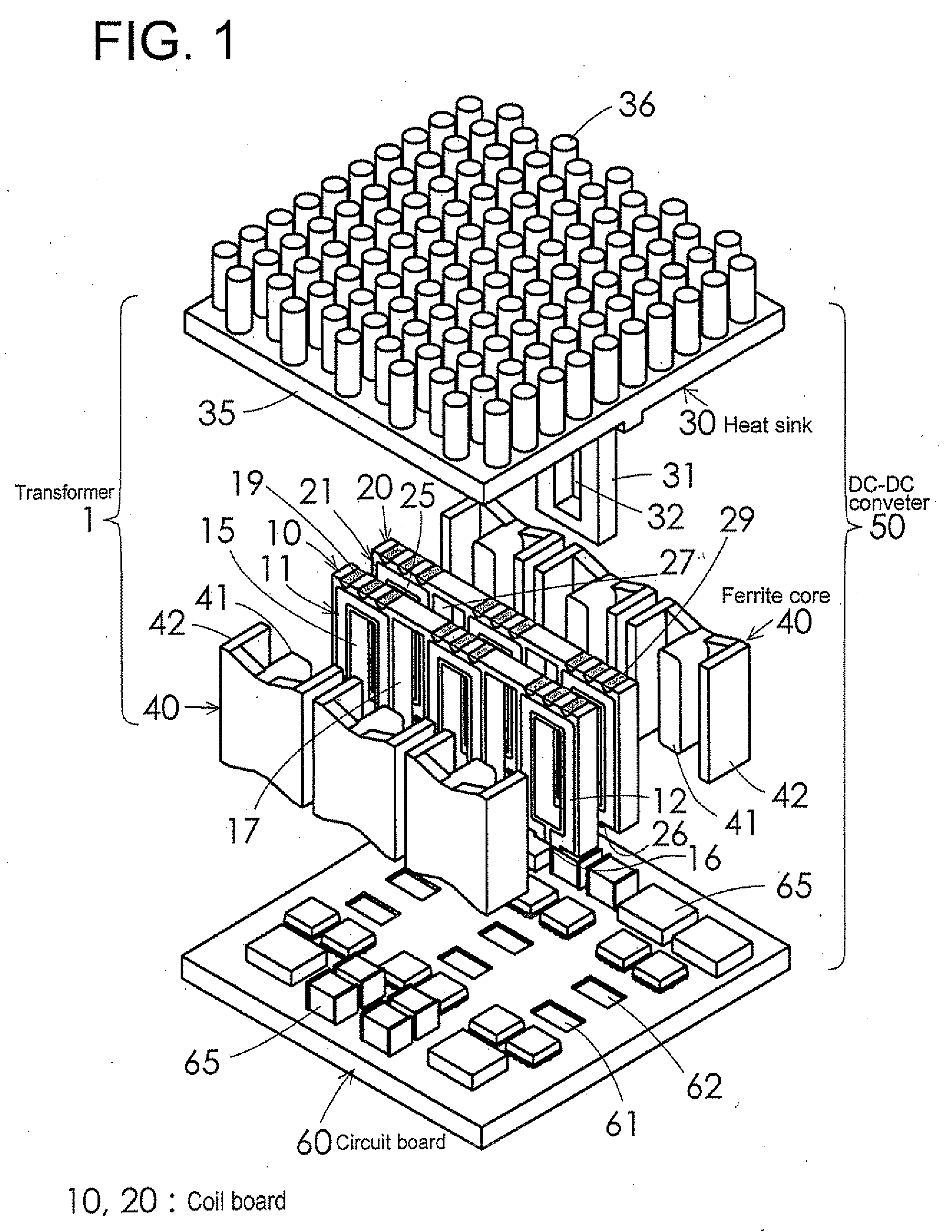
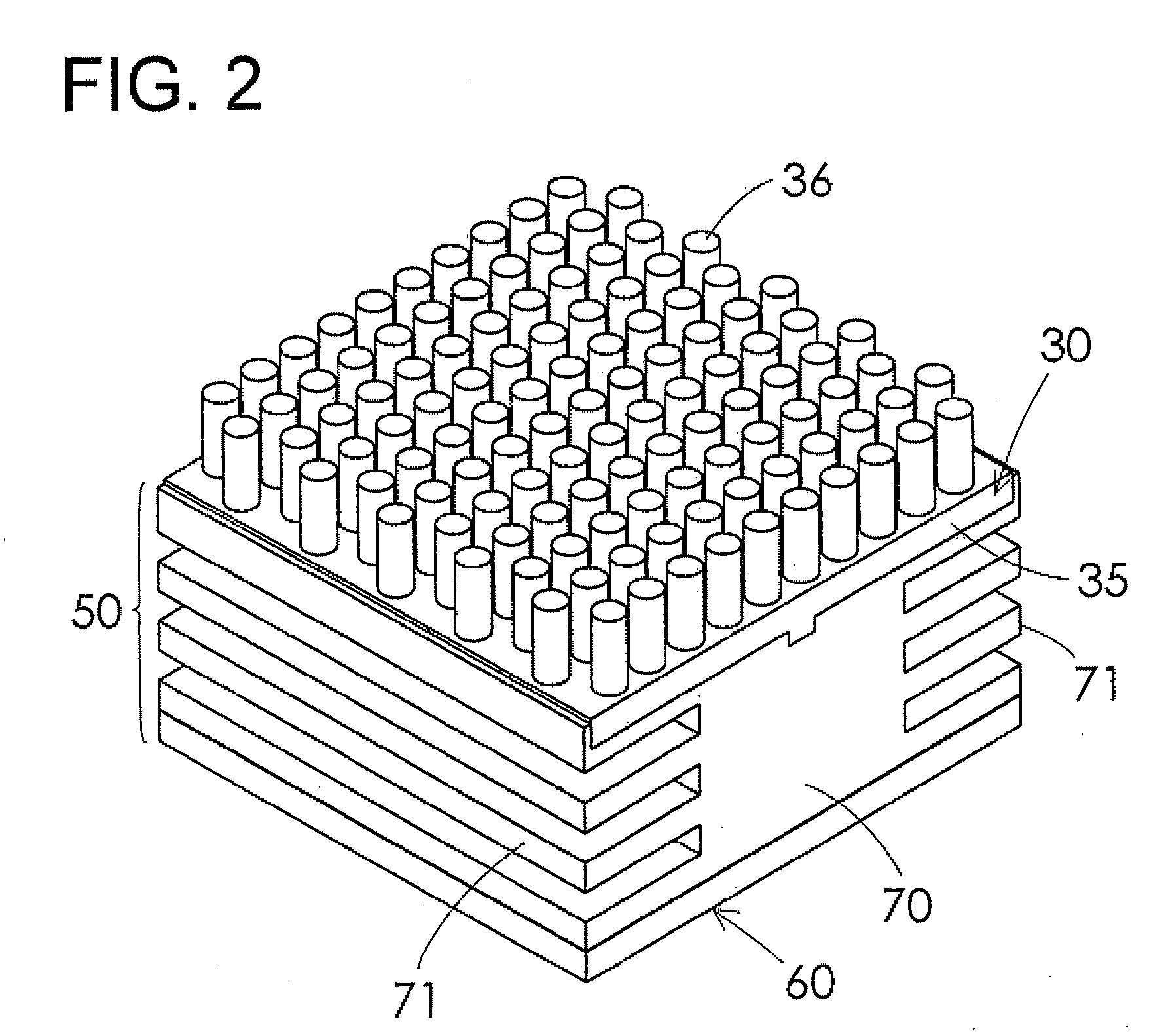
[0026]As shown in FIG. 1 to FIGS. 6A, 6B and 6C a planar transformer 1 comprises a primary coil board 10 including a primary coil 11, a secondary coil board 20 including a secondary coil 21, a heat sink 30 integrally having a spacer portion 31 which is inserted into a gap between the primary coil board 10 and the secondary coil board 20, and a ferrite core assembly as a magnetic core assembly. The ferrite core assembly consists of pairs of ferrite cores 40 that surround the first and second coil boards 10 and 20.

[0027]A DC-DC converter 50 making up a switching power supply has a structure wherein the planar transformer 1 is mounted on a circuit board 60 on which a switching device switching a current flow through the primary coil 11 and a rectifier circuit rectifying a induced voltage of the secondary coil 21 of the planar transformer 1 ...


PUM


Abstract

A planar transformer comprises a primary coil board including a primary coil, a secondary coil board including a secondary coil, a heat sink integrally having a spacer portions and a magnetic core assembly mounted to the primary coil board and the secondary coil board. The spacer portion is inserted into a gap between and facing the primary coil board and the secondary coil board and at least a surface of the heat sink is electrical insulating.

Description

BACKGROUND OF THE INVENTION[0001]1. Field of the Invention[0002]This invention relates to planar transformers having a combination of primary coil board, a secondary coil board and a magnetic core assembly, to switching power supplies using the planar transformer, and more particularly to cooling structures thereof[0003]2. Description of the Prior Art[0004]Recently, switching power supplies for electronic equipments were required to be decreased in size and thickness, thus planar transformers in which a primary coil and a secondary coil consisted of multilayer boards came to be used.[0005]Conventional planar transformers using coils such as the multilayer boards have a structure to cool down coils indirectly by fixing a cooling fin on a magnetic core. For example, it is known a structure that is disclosed in Japanese Patent Application Laid-Open No. 7-23559.[0006]However, increase of switching frequency in DC-DC converters used for switching power supplies accompanies with increase ...

Claims


Application Information

Patent Timeline
IPC IPC(8): H01F27/08
CPCF28D2021/0029H01F3/14H01F27/022H01F27/025H01F27/085H01F2027/297H01F27/2804H01F27/324H01F38/08H01F2027/2819H01F27/22
Inventor SUZUKI, NOBUAKI
Owner TDK CORPARATION
Learn More