Optical transmission apparatus and method of controlling the same

a transmission apparatus and optical technology, applied in the field of optical transmission apparatuses, can solve the problems of power decrease reception error or deterioration in communication quality, etc., and achieve the effect of maintaining the communication quality of optical signals

Inactive Publication Date: 2008-04-03
FUJITSU LTD
View PDF2 Cites 59 Cited by
  • Summary
  • Abstract
  • Description
  • Claims
  • Application Information

AI Technical Summary

Benefits of technology

[0052]As described above, according to the present invention, it is possible to control a power control device so that arrangement information of a wavelength channel for a signal light is obtained, and then, based on the obtained arrangement information, light power of a wavelength component of the signal light is made substantially equal to light power of a wavelength component other than the wavelength component of the signal light. Accordingly, advantages maybe obtained such that the transitional gain variation that is caused due to SRS and SHB when the number of signal wavelengths changes is suppressed, and it is possible to maintain the communication quality of the optical signals.

Problems solved by technology

Therefore, a problem has been noted that, when performing communication between the OADM nodes provided at multiple stages, it is expected that an amount of variation in the signal power is accumulated, and accordingly, the power of the optical signals in a receiving-side apparatus goes down below a reception range, i.e. the signals may not be recognized as signals or a signal-to-noise ratio deteriorates, thereby causing a reception error or deterioration in communication quality.
A problem has been noted that, when an amount of the accumulation of the variation in signal power becomes large, the power of optical signals goes down below a reception range, i.e. the signals may not be recognized as signals or a signal-to-noise ratio deteriorates, thereby causing a reception error or deterioration in communication quality.
Therefore, when the signal on the short wavelength side is eliminated, the remaining signal light on the long wavelength side cannot obtain power from the short wavelength side, thereby causing the power decrease.
However, in the future, an increasing number of optical amplifiers along with the increase in the distance of the system may cause the optical signals power on the reception end to exceed the tolerance level of reception, resulting in a cause of transmission error.
The technique described in Patent Document 2 does not provide any solution for such a problem.

Method used


Image

  • Optical transmission apparatus and method of controlling the same
  • Optical transmission apparatus and method of controlling the same
  • Optical transmission apparatus and method of controlling the same

Examples


Embodiment Construction

[0063]The following describes an embodiment of the present invention, with reference to the drawings.

[0064]It should be noted that, other than the above described object of the present invention, other technical problems, solutions for those technical problems and effects of such solutions also become apparent from the disclosure of the embodiment that follows.

[0065](a) Description of Embodiment

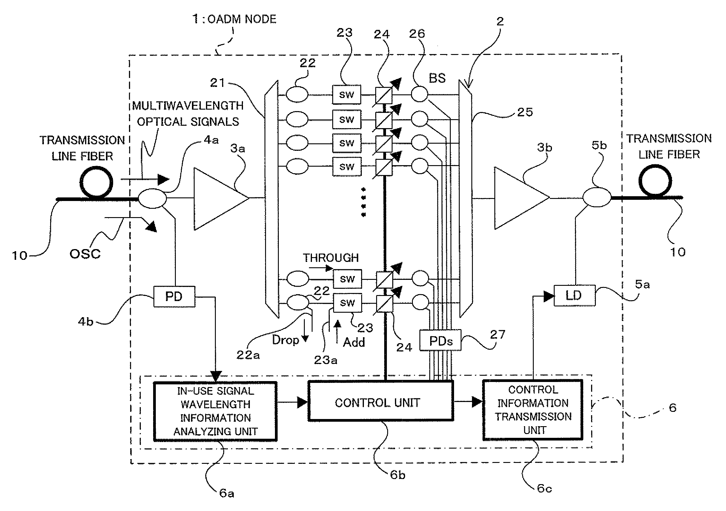
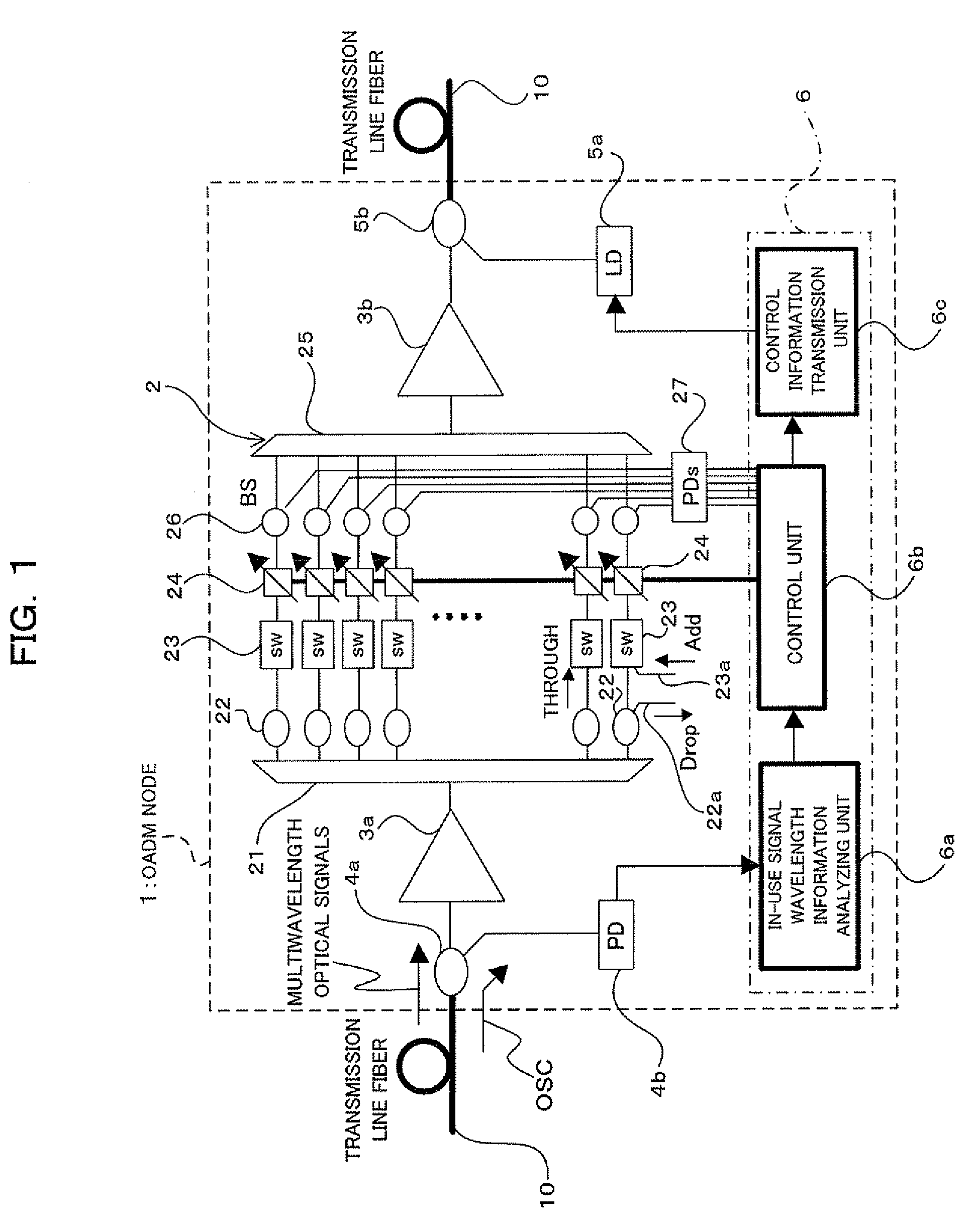
[0066]FIG. 1 is a diagram illustrating an optical transmission apparatus 1 according to one embodiment of the present invention. The optical transmission apparatus 1 shown in FIG. 1 is utilized as an OADM node in a multiwavelength optical transmission system such as a metro core system shown in FIG. 6 described above. The optical transmission apparatus 1 includes an OADM unit 2, optical amplifiers 3a and 3b provided respectively on input and output sides of the OADM unit 2, an optical coupler 4a and a photodiode 4b that are provided on the input side of the OADM unit 2, a laser diode 5a and a...


PUM


Abstract

The present invention relates to an optical transmission apparatus capable of suppressing a transitional gain variation when a number of signal wavelengths changes, and maintaining communication quality in optical signals. The optical transmission apparatus is provided with an optical power control device that varies light power of light for each wavelength component corresponding to a wavelength channel, the light including signal light and spontaneous emission light; a wavelength arrangement information obtaining unit that obtains arrangement information of the wavelength channel of the signal light; and a control unit that controls the power control device based on the arrangement information obtained at the wavelength arrangement information obtaining unit so that light power of a wavelength component of the signal light and light power of a wavelength component other than the wavelength component of the signal light become substantially equal.

Description

BACKGROUND OF THE INVENTION[0001]1. Field of the Invention[0002]The present invention relates to an optical transmission apparatus and a method of controlling the same, and in particular, to an optical transmission apparatus that is suitably used in an optical network for multiwavelength transmission of optical signals, and a method of controlling the same.[0003]2. Description of the Related Art[0004]In recent years, as one example of multiwavelength optical transmission systems, an optical network (metro core) system has been gaining attentions in which system local cities as regional bases are connected and an optical signal with a given wavelength may be added or dropped at a given node provided for a base.[0005]FIG. 6 is a block diagram showing a configuration example of a metro core system. In a multiwavelength optical transmission system 100 that constitutes the metro core system, a plurality of OADM (Optical Add-Drop Multiplexer) nodes 101 (for example, 101-1, 101-2, and 101-...

Claims


Application Information

Patent Timeline
Patent Type & Authority Applications(United States)
IPC IPC(8): H04J14/02H04B10/07H04B10/2507H04B10/2537H04B10/27H04B10/29H04B10/296H04J14/00
CPCH04J14/0204H04J14/0221H04J14/0212H04J14/0205
Inventor MURO, SHINICHIROUSUGIYA, HIDEAKISUGAYA, YASUSHIHAYASHI, ETSUKO
Owner FUJITSU LTD
Why Eureka
Try Eureka