Focused ultrasound system with far field tail suppression

a technology of ultrasound and far field, applied in the field of thermal treatment systems, can solve the problems of unusable and potentially harmful heating and necrosis of otherwise healthy tissue, and achieve the effect of reducing the risk of infection

Active Publication Date: 2008-04-03
INSIGHTEC
View PDF98 Cites 63 Cited by
  • Summary
  • Abstract
  • Description
  • Claims
  • Application Information

AI Technical Summary

Benefits of technology

[0009]In accordance with one embodiment, a procedure for treating tissue using acoustic energy includes identifying a three-dimensional target tissue ablation zone, delivering a relatively short duration pulse of acoustic energy from a transducer to generate bubbles in tissue located in a distal portion (relative to the transducer) of the target ablation zone, and, in the presence of the bubbles, delivering a substantially longer duration pulse of acoustic energy to a more proximally located focal center of the target ablation zone. In particular, the bubbles generated by the initial, short duration pulse form a “bubble mask” that suppresses formation of a far-field thermal ablation tail that would otherwise occur if the bubbles had been generated at the focal center, as is done in a conventional enhanced-ablation procedure. Because, bubbles generated by the initial, “bubble formation” pulse will rapidly dissipate, and it may be desirable to deliver additional bubble formation pulses in-between relatively longer “ablation energy” pulses, in order to re-establish and / or maintain the bubble mask in the distal portion of the target tissue ablation zone.

Problems solved by technology

Although the waves that pass through (or are reflected from) the focal zone 120 tend to diverge in the far field region 122, to the extent any such far field energy absorption occurs in a concentrated area, it can result in undesirable and potentially harmful (and painful) heating and necrosis of otherwise healthy tissue.

Method used


Image

  • Focused ultrasound system with far field tail suppression
  • Focused ultrasound system with far field tail suppression
  • Focused ultrasound system with far field tail suppression

Examples


Embodiment Construction

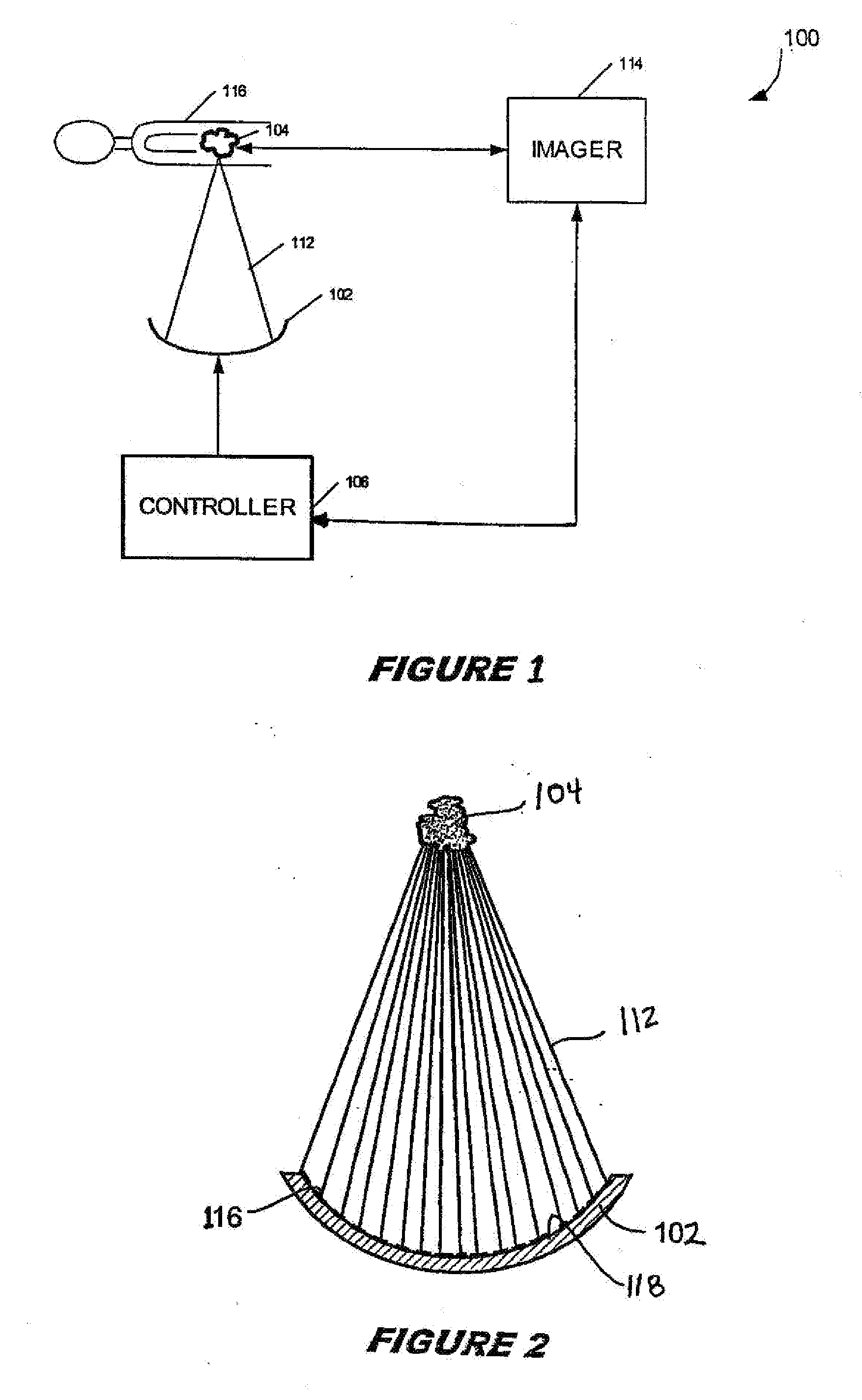
[0027]It will be appreciated that embodiments of the invention may be software and / or hardware implemented in a control system of a focused ultrasound system, e.g., such as controller 106 of system 100 shown in FIG. 1. Further embodiments of the invention include methods for using a focused ultrasound system to deliver converging acoustic wave energy to a selected three-dimensional focal zone in a target tissue region for providing controlled thermal dosing of body tissue, which methods may manually controlled, or which may be fully or partially automated. In particular, embodiments of the invention may be implemented in systems and methods for providing and controlling a series of treatment sonications for ablating a target tissue region, and may involve one or both of user input and control (e.g., operational commands entered through a user interface), and automated functions performed by the system controller. In accordance with this general understanding, the following detailed ...


PUM


Abstract

A method for treating body tissue using acoustic energy includes identifying a target focal zone of tissue to be treated, delivering a first pulse of acoustic energy from a transducer to generate bubbles in a tissue region located distally, relative to the transducer, of a focal center of the target focal zone, and delivering a second pulse of acoustic energy from the transducer in the presence of the bubbles generated by the first pulse, the second pulse focused at the focal center to generate thermal ablation energy. In a further embodiment, a method of treating body tissue using ultrasound energy includes identifying a target focal zone to be treated and delivering a plurality of pulses of acoustic ablation energy to locations distributed symmetrically in or proximate a focal plane about the focal center of the target focal zone.

Description

RELATED APPLICATION DATA[0001]This application claims the benefit of U.S. Utility patent application Ser. No. 11 / 380,332, filed Apr. 26, 2006, pursuant to 35 U.S.C. Section 120, and any other applicable laws. The aforementioned application is hereby incorporated by reference herein in its entirety.FIELD OF INVENTION[0002]The present invention relates generally to thermal treatment systems, and more particularly to systems and methods for delivering and controlling thermal energy dosing using an image-guided, focused ultrasound system.BACKGROUND[0003]It is well-known to use high intensity, focused acoustic wave energy, such as ultrasonic waves (i.e., acoustic waves having a frequency greater than about 20 kilohertz) to generate thermal ablation energy for treating internal body tissue, such as tumors. It is also well-known to employ a tissue imaging system (e.g., MRI) in order to guide the delivery of such high intensity ultrasound energy, and to provide real-time feedback. One such ...

Claims


Application Information

Patent Timeline
Patent Type & Authority Applications(United States)
IPC IPC(8): A61N7/00
CPCA61B2017/00176A61N7/02A61B2019/5236A61B2017/22008A61B2090/374
Inventor SCHMIDT, RITAVITEK, SHUKI
Owner INSIGHTEC
Why Eureka
Try Eureka