
Automata unit, a tool for designing checker circuitry and a method of manufacturing hardware circuitry incorporating checker circuitry

Inactive Publication Date: 2008-04-03
MCGILL UNIV
View PDF6 Cites 76 Cited by
  • Summary
  • Abstract
  • Description
  • Claims
  • Application Information

AI Technical Summary

Problems solved by technology

As a result of the increasing complexity, verifying that the design intent is faithfully implemented is becoming the dominant task within the overall project.
The cost to design a new device is subject to many factors such as; re-use of IP (Intellectual Property) blocks, process technologies, complexity, and company specific overheads.
Examples of defects in ICs range from satellite and rocket malfunctions, to glitches and failures in consumer applications.
One well-known case is the floating-point error found on early models of the Pentium processor by Intel.
In today's complex hardware digital circuit designs, verification typically requires more effort than the actual design phase itself.
Although a large number of simulations can be run, the effort spent in fixing the bugs does not resolve the question of whether the design is faithful.
A heavy burden is placed on design teams to prioritize which design areas need special attention and to identify events which could trigger a catastrophic failure.
For those reasons, the ITRS suggests that without new techniques, verification will be a barrier for progress in the industry.
Like finding the proverbial needle in the haystack, debugging increasingly complex devices can easily become a roadblock to delivering the end product on time.
Furthermore, when design errors are found during emulation, additional information from the assertion checkers should be used to point to the source of the problem.
Coding checkers by hand can be a tedious and error-prone task.

Method used


Image

  • Automata unit, a tool for designing checker circuitry and a method of manufacturing hardware circuitry incorporating checker circuitry
  • Automata unit, a tool for designing checker circuitry and a method of manufacturing hardware circuitry incorporating checker circuitry
  • Automata unit, a tool for designing checker circuitry and a method of manufacturing hardware circuitry incorporating checker circuitry

Examples


Embodiment Construction

The Industry Context

[0039]In typical circuit designing, after errors have been identified by simulation, the next step is to debug the design. Like finding the proverbial needle in the haystack, debugging increasingly complex devices can easily become a roadblock to delivering the end product on time. To address this issue, a number of companies and researchers have proposed solutions, which provide deeper on-chip observability and have formed an industry organization, Design for Debug (DFD) to promote this market segment. In line with these goals, the present invention provides increased activity monitoring and observability during the debugging stage. Furthermore, if checkers circuitry is incorporated in the final circuit design, in-circuit diagnostic routines can be implemented during field deployment. This represents a significant value-added feature for systems in mission critical environments.

[0040]The leading Field Programmable Gate Arrays (FPGA) device vendors, Altera™, Xili...


PUM


Abstract

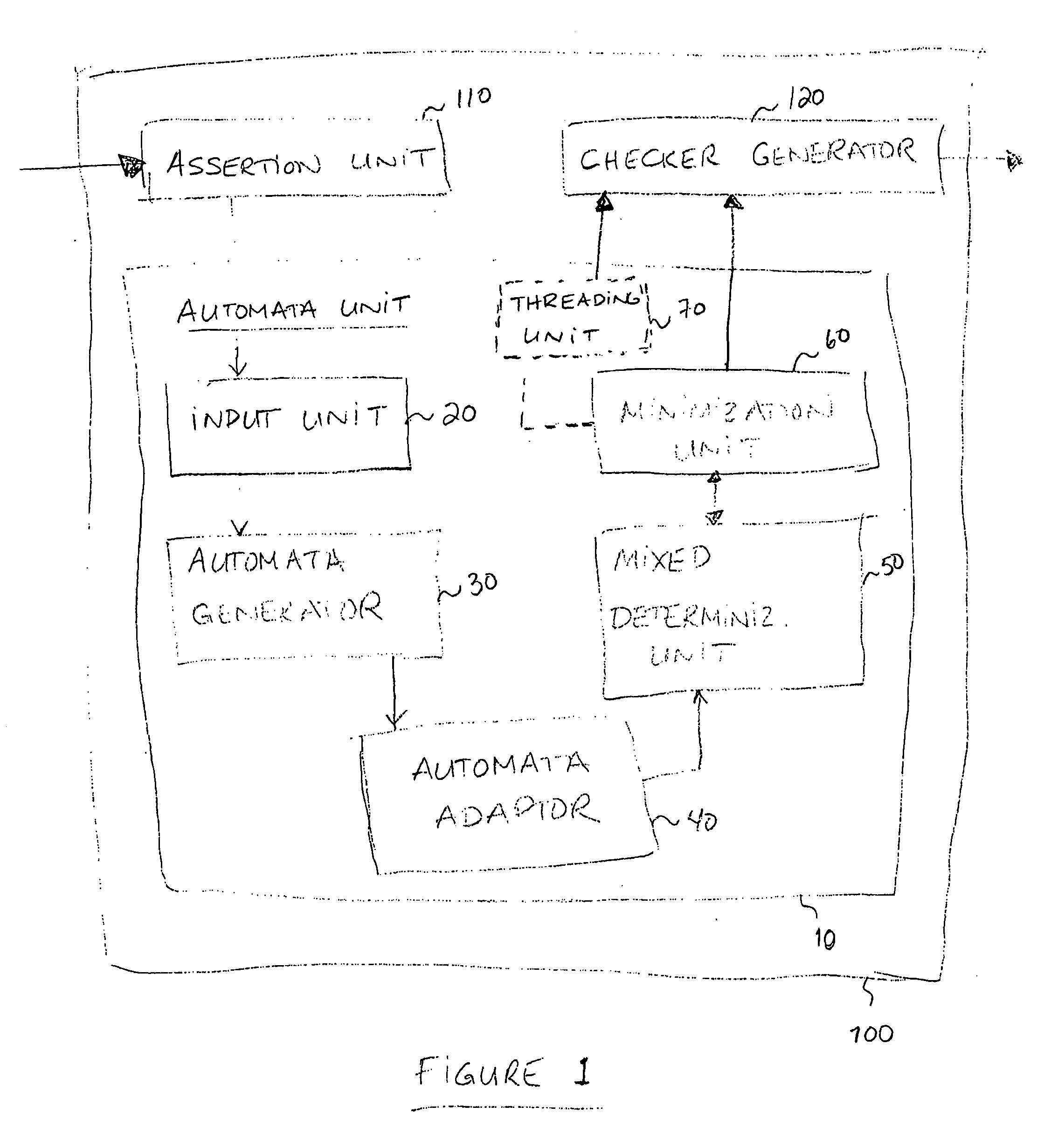
The present invention relates to an automata unit, a tool for designing circuitry and / or checker circuitry, and a method for manufacturing hardware circuitry. The automata unit includes an input unit for receiving assertions using Boolean expressions, an automata generator for translating the assertions into automata, and an automata adaptor. The automata generator uses a dual layer symbolic alphabet for representing the assertions, and the automata adaptor adapts automata algorithms so as to support the symbolic alphabet in the generated automata. The tools for designing circuitry and checker circuitry rely on the automata unit, and further include an assertion unit and either a circuit generator or a checker generator.

Description

FIELD OF THE INVENTION[0001]The present invention relates to the field of hardware circuitry and more particularly to the field of generation, design and manufacturing of assertion checker circuitry.BACKGROUND OF THE INVENTION[0002]In 1965, Gordon Moore suggested the number of transistors in devices will approximately double every two years. This observation, widely known as Moore's Law, is still valid today. The pace of innovation of process technology has been nothing short of remarkable. The industry is currently working on 65 and 45 nanometer designs, enabling billion transistor devices. The size of the industry is equally impressive. The Semiconductor Industry Association estimated that sales for 2006 for integrated circuit devices would be over $207 Billion US and over $262 Billion by 2008. There seems to be no end to the demand for new and more complex products requiring integrated circuits.[0003]Engineers use Electronic Design Automation (EDA) tools to develop and manufactur...

Claims


Application Information

Patent Timeline
IPC IPC(8): G06F17/50
CPCG06F17/504G06F30/3323
Inventor ZILIC, ZELJKOBOULE, MARC
Owner MCGILL UNIV
Learn More