Standalone thermal energy recycling device for engine after-treatment systems

Inactive Publication Date: 2008-04-10
YAN MI
View PDF6 Cites 36 Cited by
  • Summary
  • Abstract
  • Description
  • Claims
  • Application Information

AI Technical Summary

Benefits of technology

[0023]In accordance with an advantageous feature of the invention, the heat exchange device intrinsically protects the SCR (or the LNT) from being damaged by thermal runaways in the DPF.
[0024]Yet in another embodiment of the present invention, the after-treatment system comprises a DOC, a DPF, an LNT, and a heat exchange device, in which high temperature exhaust air emit from th

Problems solved by technology

However, due to high exhaust flow rate, most of regeneration energy is actually used for increasing enthalpy of exhaust air instead of providing enough temperature for soot to be oxidized or for reducing metal sulfate.
Due to the large power needed in regeneration, resistive heating devices normally cannot be directly used for mobile applications without exhaust flow control, while fuel

Method used


Image

  • Standalone thermal energy recycling device for engine after-treatment systems
  • Standalone thermal energy recycling device for engine after-treatment systems
  • Standalone thermal energy recycling device for engine after-treatment systems

Examples


Embodiment Construction

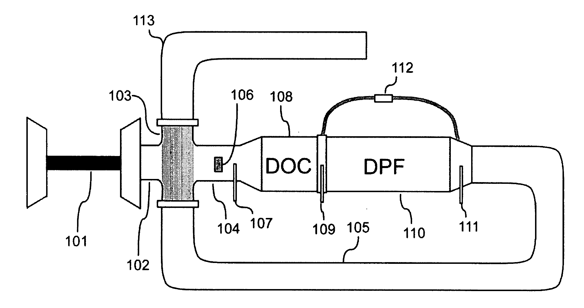
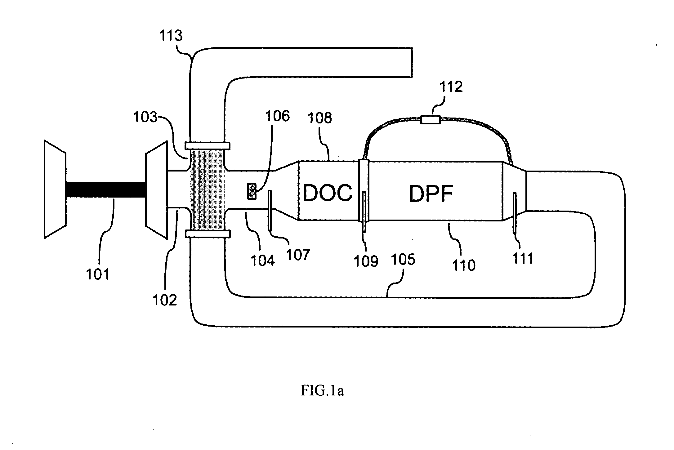
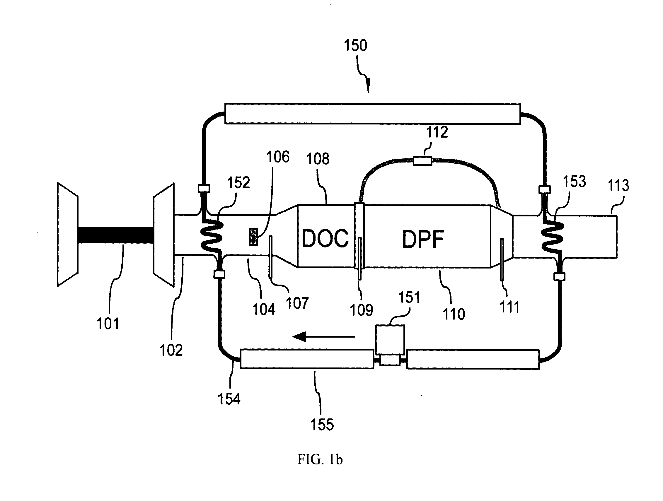
[0036]As depicted in FIG. 1, in an after-treatment system, a standalone heat exchange device 103 is connected with a turbocharger 101 through a pipe 102. Another pipe 104 is used to connect the heat exchange device 103 to a DOC 108, in which the HC, CO, and NOx are oxidized. Particulate matter (PM) generated by the engine is trapped in a DPF 110. A pipe 105 connects the DPF 110 back to the heat exchange device 103, and a pipe 113 conducts exhaust air off the after-treatment system.

[0037]When certain amount of PM deposits in the DPF 110, a regeneration process is triggered, and HC injected from a doser 106 is oxidized in the DOC 108 to provide heat for burning off PM in the DPF 110. During the regeneration process, the DOC inlet temperature is measured by a thermistor 107, while the DOC outlet temperature is monitored by using a thermistor 109. To effectively monitor the DOC conversion efficiency and detect thermal runaways inside the DPF, a thermistor 1111 is connected to the outlet...


PUM


Abstract

A standalone thermal energy recycling device in which exhaust air emitted from an internal combustion engine exchanges heat with that being heated during regeneration of after-treatment devices. By using the thermal energy recycling device, heat generated for regeneration is used to compensate energy loss during heat exchange rather than provide the overall energy needed for boosting exhaust flow temperature to target. Inside the thermal energy recycling device, heat exchanger is bypassed during normal engine operations for decreasing back pressure.

Description

[0001]This present application claims priority from U.S. provisional application No. 60 / 850,459 having the title of Engine Aftertreatment System with Thermal Energy Recycling and filed on Oct. 10, 2006.FIELD OF THE INVENTION[0002]The present invention relates to devices for effectively boosting and controlling temperature of exhaust gases emitted from an internal combustion engine to facilitate regeneration of after-treatment systems.BACKGROUND OF THE INVENTION[0003]Reducing oxides of nitrogen (NOx), carbon monoxide (CO), hyrdrocarbon (HC), and particulate matter (PM) in exhaust air from internal combustion engines is required in emission control. DOCs (Diesel Oxidation Catalyst) and three-way catalysts have been broadly used for reducing CO, HC, and NOx, while SCR (Selective Catalytic Reduction), LNT (Lean NOx Trap, a.k.a. NOx adsorber), LNC (Lean NOx Catalyst), and EGR (Exhaust Gas Recirculation) technology are used for achieving low NOx emissions. The PM in exhaust air usually is...

Claims


Application Information

Patent Timeline
IPC IPC(8): F01N3/025F01N3/035
CPCF01N3/0205F01N3/0234Y02T10/16F01N3/035F01N5/02F01N3/025Y02T10/12
Inventor YAN, MI
Owner YAN MI
Why Eureka
Try Eureka