Method for electrically energizing and heating platinum composite tube structure

a composite tube and platinum alloy technology, applied in the direction of glass reforming apparatus, glass tempering apparatus, glass pressing apparatus, etc., can solve the problems of adversely affecting the quality of molten glass, inability to electrically energize and heat the corner, etc., to eliminate such reboiling, reduce the amount of bubbles in the molten glass, and eliminate such reboiling

Active Publication Date: 2008-04-10
ASAHI GLASS CO LTD
View PDF5 Cites 24 Cited by
  • Summary
  • Abstract
  • Description
  • Claims
  • Application Information

AI Technical Summary

Benefits of technology

[0028] When the composite tube structure is a part of a conduit for molten glass, the electrical heating method of the present invention has the following additional effects.
[0029] Molten glass may remain in a dead space in the composite tube structure, depending on the path of molten glass in the composite tube structure, in some cases. The quality of the molten glass remaining in the dead space has deteriorated in many cases, and if a part of the molten glass remaining in the dead space gets into the molten glass in a main flow, the quality of the molten glass in the main flow could deteriorate. The electrical heating method according to the present invention can prevent molten glass remaining in the dead space of the composite tube structure from getting into the main flow, without lowering the temperature of molten glass on the exit side of the composite tube structure, or can eliminate such mixing. Accordingly, the quality of molten glass flowing in the composite tube structure will not be adversely affected.
[0030] When the composite tube structure serves as a conduit on the downstream side of a vacuum degassing vessel in a vacuum degassing apparatus, reboiling (the phenomenon of forming bubbles again) could occur in the molten glass flowing in the composite tube structure under excessive heating or under a reduced pressure. Similarly, when the composite tube structure serves as a conduit on the downstream aide of a vacuum degassing apparatus, reboiling could occur in the molten glass flowing in the composite tube structure. The electrical heating method of the present invention can prevent reboiling from occurring in molten glass flowing in the composite tube structure, without lowering the temperature of the molten glass on the exit side of the composite tube structure, or can eliminate such reboiling. Consequently, the amount of bubbles in the molten glass can be reduced, thus preventing an adverse effect on the quality of the molten glass.
[0031] When the composite tube structure serves as a conduit on the upstream side of the vacuum degassing vessel in the vacuum degassing apparatus or a conduit on is the upstream side of the vacuum degassing apparatus, the electrical heating method of the present invention has favorable effects. Namely, since molten glass flowing in the composite tube structure will not forms bubbles or deflected streams, the vacuum degassing effects of the vacuum degassing vessel will not be adversely affected.
[0032] The glass manufacturing method of the present invention obtains the above-described effects of the electrical heating method of the present invention, and can electrically energize and heat, the whole composite tube structure forming a conduit for molten glass to a desired temperature without excess or deficiency, so that the quality of molten glass flowing in the composite tube structure will not be adversely affected.

Problems solved by technology

At worst, it may be impossible to electrically energized and heat the corner 105a to the desired temperature.
If the corner 105a cannot be electrically energized and heated to the desired temperature, there is a possibility that bubbles or deflected streams are formed in molten glass flowing in the composite tube structure 100, adversely affecting the quality of the molten glass.

Method used


Image

  • Method for electrically energizing and heating platinum composite tube structure
  • Method for electrically energizing and heating platinum composite tube structure
  • Method for electrically energizing and heating platinum composite tube structure

Examples


Embodiment Construction

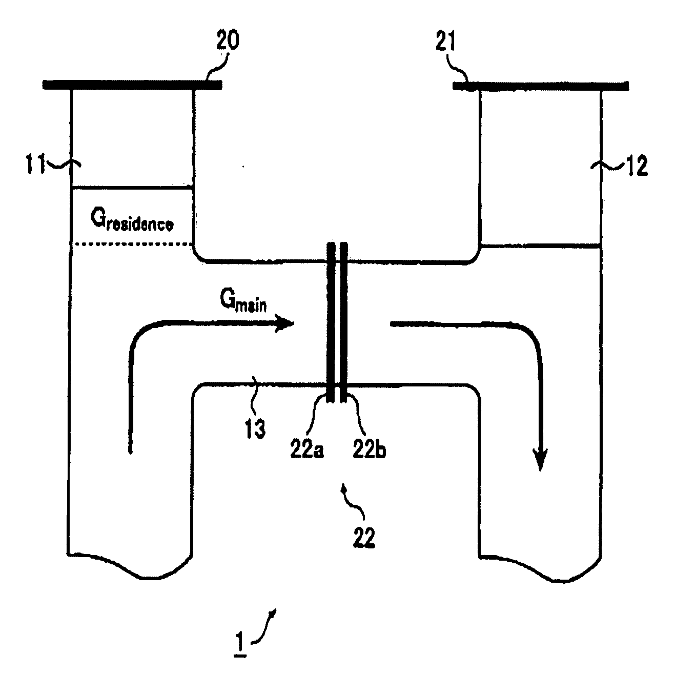
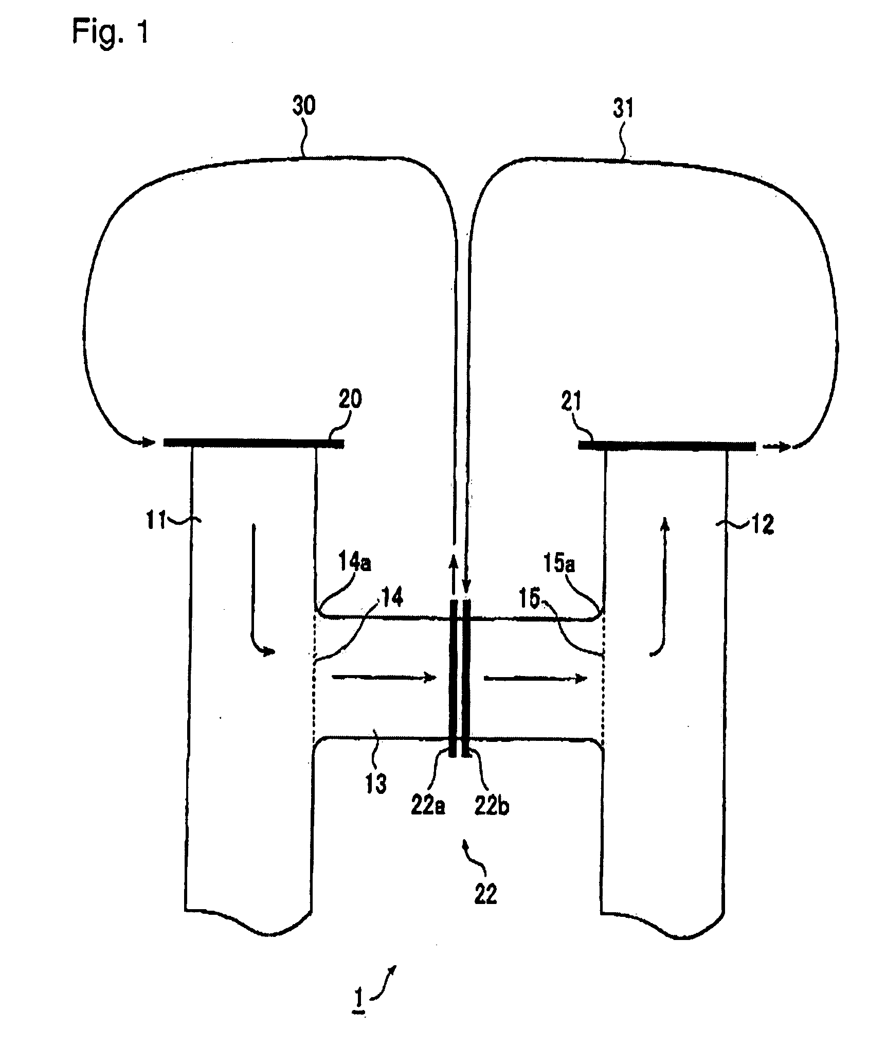
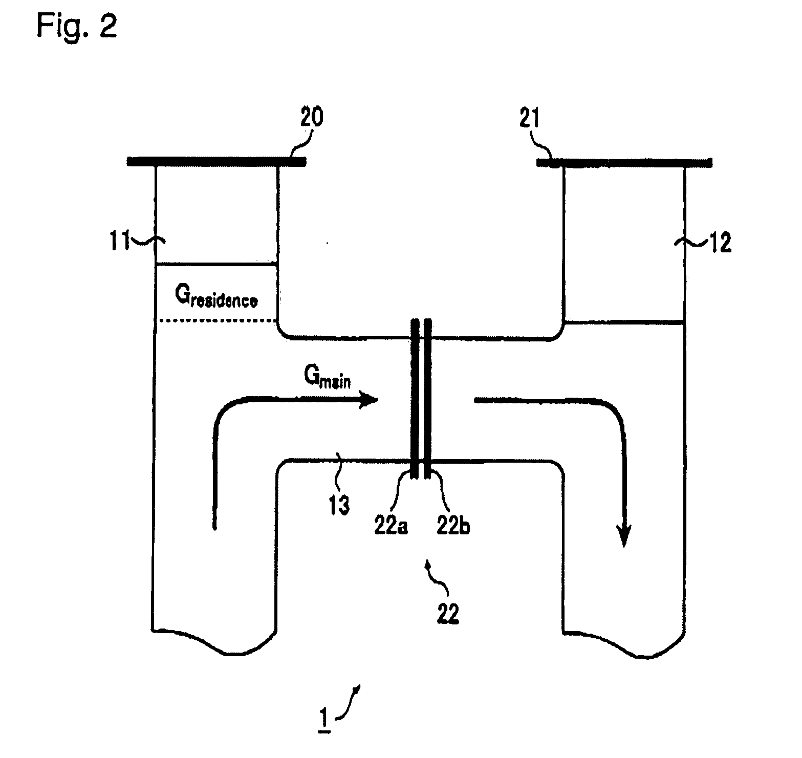
[0036] The present invention will be described with reference to the drawings. FIG. 1 is a schematic view illustrating an electrical heating method of the present invention and shows a composite tube structure 1 to be electrically energized and heated, according to an embodiment of the present invention. The composite tube structure 1 shown in FIG. 1 includes two main tubes 11 and 12 and a branch tube 13 connecting the main tube 11 and the main tube 12. The main tubes 11 and 12 and the branch tube 13 comprise platinum or platinum-alloy hollow tubes. The platinum alloy may be, for example, platinum-gold alloy or platinum-rhodium alloy. Parts made of platinum or a platinum alloy here include parts made from reinforced platinum produced by dispersing a metal oxide in platinum or a platinum alloy. The metal oxides dispersed here include oxides of metal in group 3, 4, or 13 in the periodic table, such as Al2O3, ZrO2, and Y2O3.

[0037] In the electrical heating method of the present invent...


PUM

PropertyMeasurementUnit
distanceaaaaaaaaaa
lengthaaaaaaaaaa
inner diameteraaaaaaaaaa

Abstract

There is provided a method for electrically energizing and heating a platinum or platinum-alloy composite tube structure having a structure including a first main tube, a second main tube, and a branch tube connecting the first main tube and the second main tube, which prevents a local part of the branch tube from being electrically energized and heated in an excessive or insufficient manner. There is provided a method for electrically energizing and heating a platinum or platinum-alloy composite tube structure having a structure including a first main tube, a second main tube, and a branch tube connecting the first main tube and the second main tube, the method comprising dividing an energizing path for the branch tube into a first energizing path from the first main tube to the branch tube and a second energizing path from the branch tube to the second main tube; and performing energization control for the first energizing path and energization control for the second energizing path independently of each other.

Description

BACKGROUND OF THE INVENTION [0001] 1. Field of the Invention [0002] The present invention relates to a method for electrically energizing and heating a platinum or platinum-alloy composite tube structure (hereafter referred to as “the electrical heating method according to the present invention”). In the present invention, the platinum or platinum-alloy composite tube structure includes a structure having two main tubes and a branch tube coupling the main tubes. The two main tubes and the branch tube in the composite tube structure are hollow tubes made of platinum or a platinum alloy. The composite tube structure is used as a conduit for molten glass in a glass manufacturing apparatus, such as a vacuum degassing apparatus. The present invention relates to a method for electrically energizing and heating the composite tube structure, and more specifically, to a method for electrically energizing and heating the branch tube in the composite tube structure. [0003] The present inventio...

Claims


Application Information

Patent Timeline
Patent Type & Authority Applications(United States)
IPC IPC(8): C03B7/14C03B7/00H05B3/12
CPCC03B7/07C03B5/2252C03B5/20C03B5/225C03B5/235H05B3/00
Inventor NAGNO, SEIHIRABARA, YASUHARUITOH, HAJIME
Owner ASAHI GLASS CO LTD
Why Eureka
Try Eureka