Oil Pan Apparatus

a technology of oil pan and oil pan, which is applied in the direction of mechanical equipment, crankshafts, machines/engines, etc., can solve the problems the oil temperature in the first chamber is not readily rising, and the oil-pan-attached machine is not properly lubricated, etc., and achieves the effect of early oil deterioration or other problems

Inactive Publication Date: 2008-04-10
TOYOTA JIDOSHA KK
View PDF9 Cites 21 Cited by
  • Summary
  • Abstract
  • Description
  • Claims
  • Application Information

AI Technical Summary

Benefits of technology

[0008] When the open/close valve becomes defective, the oil-pan-attached machine is not properly lubricated. If, for instance, the valve is stuck open (this failure is hereinafter referred to as “open valve failure”), the open/close valve remains open immediately after engine startup during which the oil temperature is low (and the oil in the oil pan apparatus can be entirely circulated between the lubrication target mechanism and oil pan apparatus). Therefore, the oil temperature in the first chamber does not readily rise. As a result, the warm-

Problems solved by technology

When the open/close valve becomes defective, the oil-pan-attached machine is not properly lubricated.
Therefore, the oil temperature in the first chamber does not readily rise.
If, on the other hand, the valve is stuck closed (this failure is hereinafter referred to as a closed valve failure), the open/close valve remains closed (and only the oil in the first chamber can be circulated between the lubricati

Method used


Image

  • Oil Pan Apparatus
  • Oil Pan Apparatus
  • Oil Pan Apparatus

Examples


first embodiment

OIL PAN APPARATUS CONFIGURATION

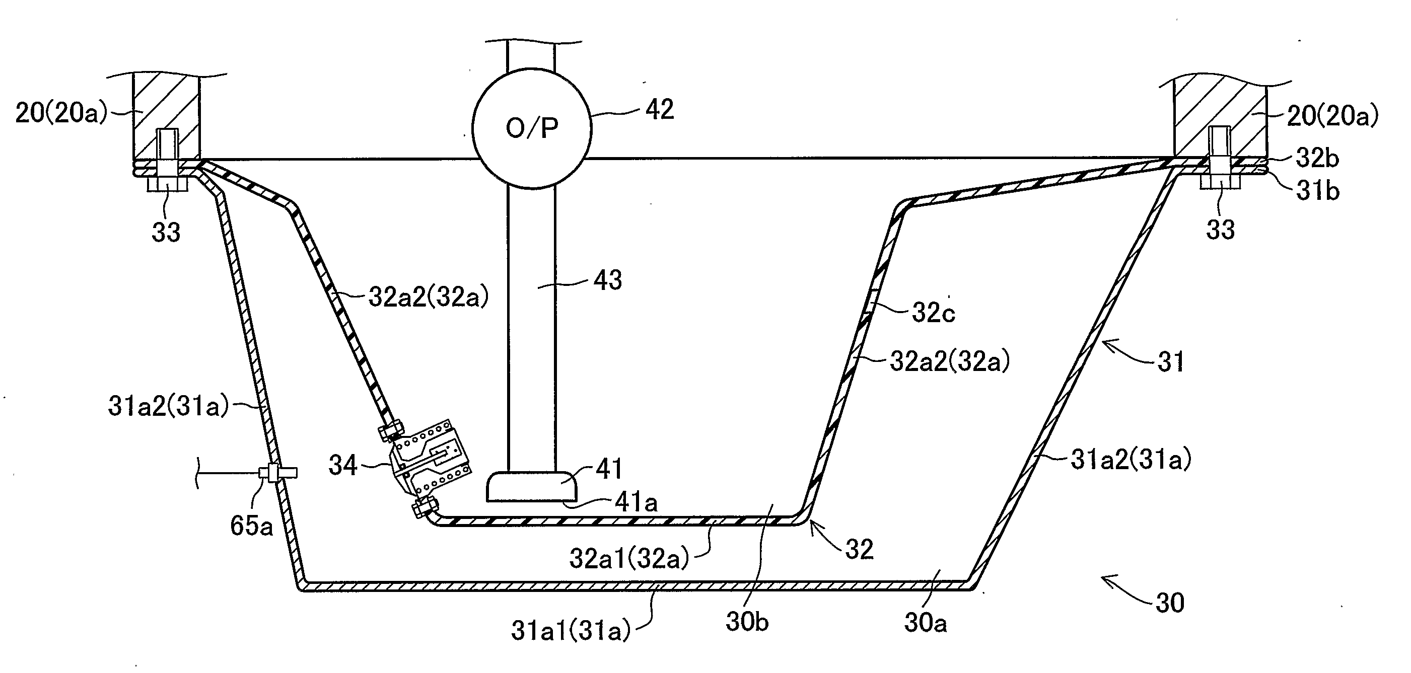
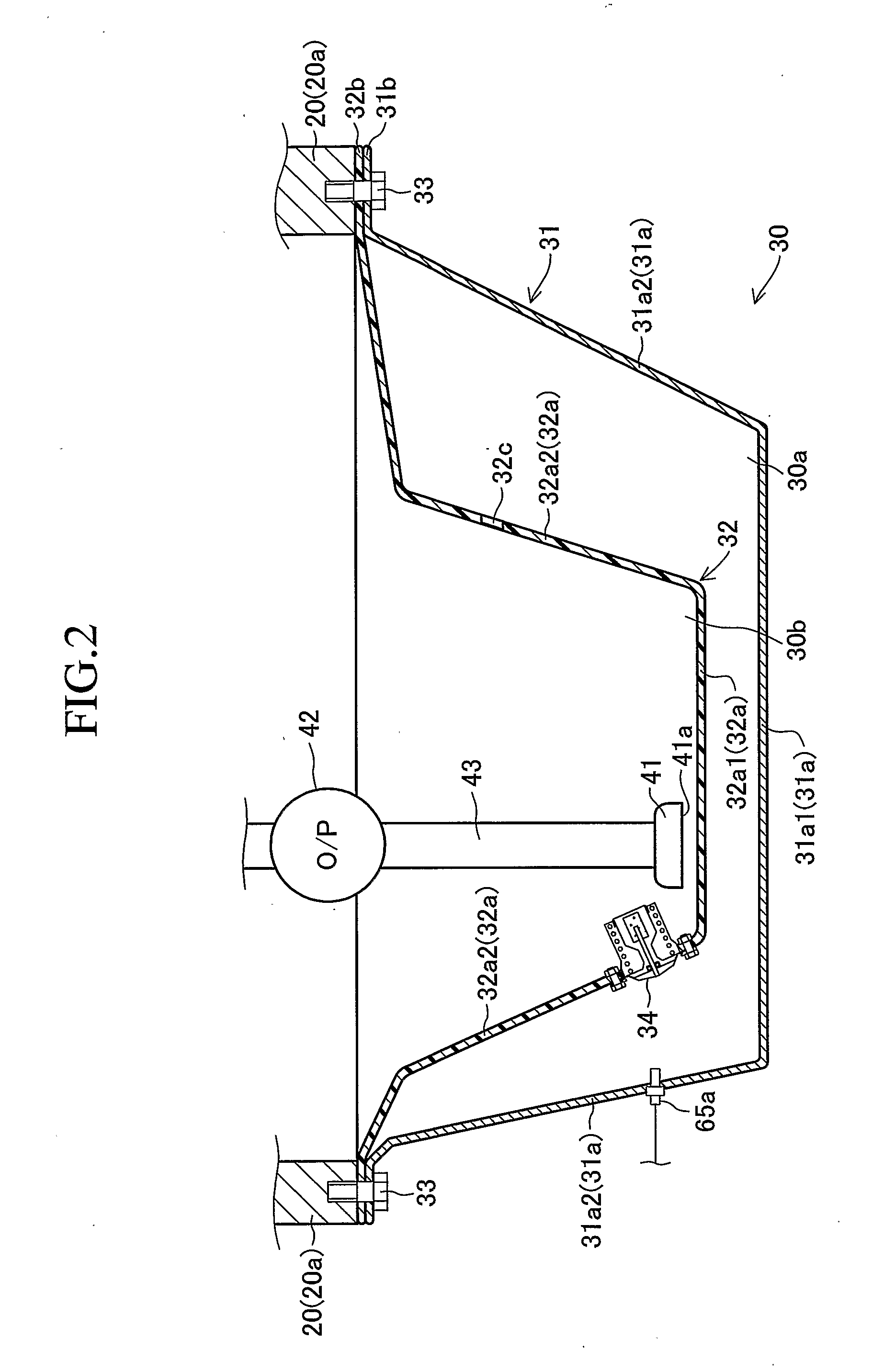
[0044]FIG. 2 is an enlarged lateral cross-sectional view illustrating a section of the oil pan apparatus 30 in the engine 10 that is shown in FIG. 1.

[0045] An oil pan cover 31 is a bathtub-shaped (concave) member that constitutes an outer cover of the oil pan apparatus 30. It is formed by pressing a steel plate and constructed of one piece. The oil pan cover 31 includes an oil storage section 31a, which is shaped like a bathtub to store oil in the internal space. At a peripheral border of a bottom plate 31a1 of the oil pan cover 31, which constitutes the bottom surface of the oil storage section 31a, a side plate 31a2 is provided and oriented obliquely upward as indicated in FIG. 2 (so that the area enclosed by the side plate 31a2 increases with an increase in the height). A flange section 31b is formed so that it extends substantially in a horizontal direction from the upper border of the side plate 31a2 to the outside. The flange section 31b is fast...

second embodiment

OIL PAN APPARATUS CONFIGURATION

[0100]FIG. 10 is a lateral cross-sectional view that schematically illustrates the configuration of an oil pan apparatus 30′ according to a second embodiment of the present invention. Elements common to the first embodiment described above will not be described herein. When such elements are depicted in the drawings, they are assigned the same reference numerals as those used in conjunction with the first embodiment.

[0101] The oil pan apparatus 30′ according to the second embodiment has the same configuration as the oil pan apparatus 30 according to the first embodiment, and includes an oil temperature sensor 65b that is mounted on the side plate 32a2 of the oil pan separator 32 to acquire the temperature of the oil in the first chamber 30a. In the configuration according to the second embodiment, oil temperature sensors 65a and 65b are used to determine the actual behavior of the oil temperatures in the first and second chambers shown in FIG. 5 so th...


PUM


Abstract

An oil temperature sensor is externally mounted on a side plate of an oil pan cover that constitutes an external cover for an oil pan apparatus. The oil temperature sensor can output a signal in accordance with the oil temperature prevailing near a thermostat valve apparatus in a second chamber. If the second chamber oil temperature rises immediately after startup of an engine, a CPU judges that an open valve failure has occurred, that is, the thermostat valve apparatus is stuck open. If the oil temperature of the second chamber is not raised when an adequate amount of time has elapsed after the end of a warm-up operation, the CPU judges that a closed valve failure has occurred, that is, the thermostat valve apparatus is stuck closed.

Description

TECHNICAL FIELD [0001] The present invention relates to an oil pan apparatus for storing oil for lubricating a lubrication target mechanism (e.g., engine block or automatic transmission mechanism). BACKGROUND ART [0002] In general, an oil pan apparatus of the above type is fastened to the underside of a lubrication target mechanism, and is configured so as to store oil in the internal space of an oil pan cover, which constitutes an outer cover for the oil pan apparatus. An oil-pan-attached machine (e.g., engine or automatic transmission device), which is equipped with the oil pan apparatus, is configured so that an oil pump takes in the oil from an oil intake port of an oil strainer, which is positioned in the oil pan apparatus, and supplies the oil to lubrication target members (e.g., gear, camshaft, cylinder, and piston) in the lubrication target mechanism. Further, the oil-pan-attached machine is configured so that the oil, which is supplied to the lubrication target members as d...

Claims


Application Information

Patent Timeline
IPC IPC(8): F16N29/00F01M11/10F16N31/00
CPCF01M5/02F01M2011/0045F01M11/0004
Inventor KOBAYASHI, HIDEOARISAWA, KATUHIKOYAMASHITA, YOSHIOHAYASHI, KUNIHIKO
Owner TOYOTA JIDOSHA KK
Why Eureka
Try Eureka