Stepping Motor

a stepping motor and stepping plate technology, applied in the direction of rotating magnets, instruments, synchronized machines with stationary armatures, etc., can solve the problems of low drive responsiveness, inability to obtain desired driving torque, and small magnetic force, so as to achieve accurate keeping and facilitate assembly operation

Active Publication Date: 2008-04-10
MITSUBISHI MATERIALS CMI CORP
View PDF4 Cites 13 Cited by
  • Summary
  • Abstract
  • Description
  • Claims
  • Application Information

AI Technical Summary

Benefits of technology

[0017] Further, according to the present invention, the outer peripheral surface of the magnet is made the cylindrical surface of the constant diameter, and therefore, the gap between the magnet and the stator can be accurately kept as in the prior art though the magnet is given the wall thickness distribution.
[0018] In addition, the magnet can be reliably prevented from idling in the circumferential direction of the magnet by the projection formed on the outer periphery of the rotor body.
[0019] Further, according to the present invention, the cavities are provided at the both end inner

Problems solved by technology

However, in the above described conventional stepping motor, there is the problem that the magnetic force becomes small and desired driving torque cannot be obtained if the wall thickness is made small, when the entire magnet 72 is constructed to be of the same wall thickness as describ

Method used


Image

  • Stepping Motor
  • Stepping Motor
  • Stepping Motor

Examples


Embodiment Construction

[0039] Hereinafter, an embodiment of the present invention will be explained with reference to the drawings.

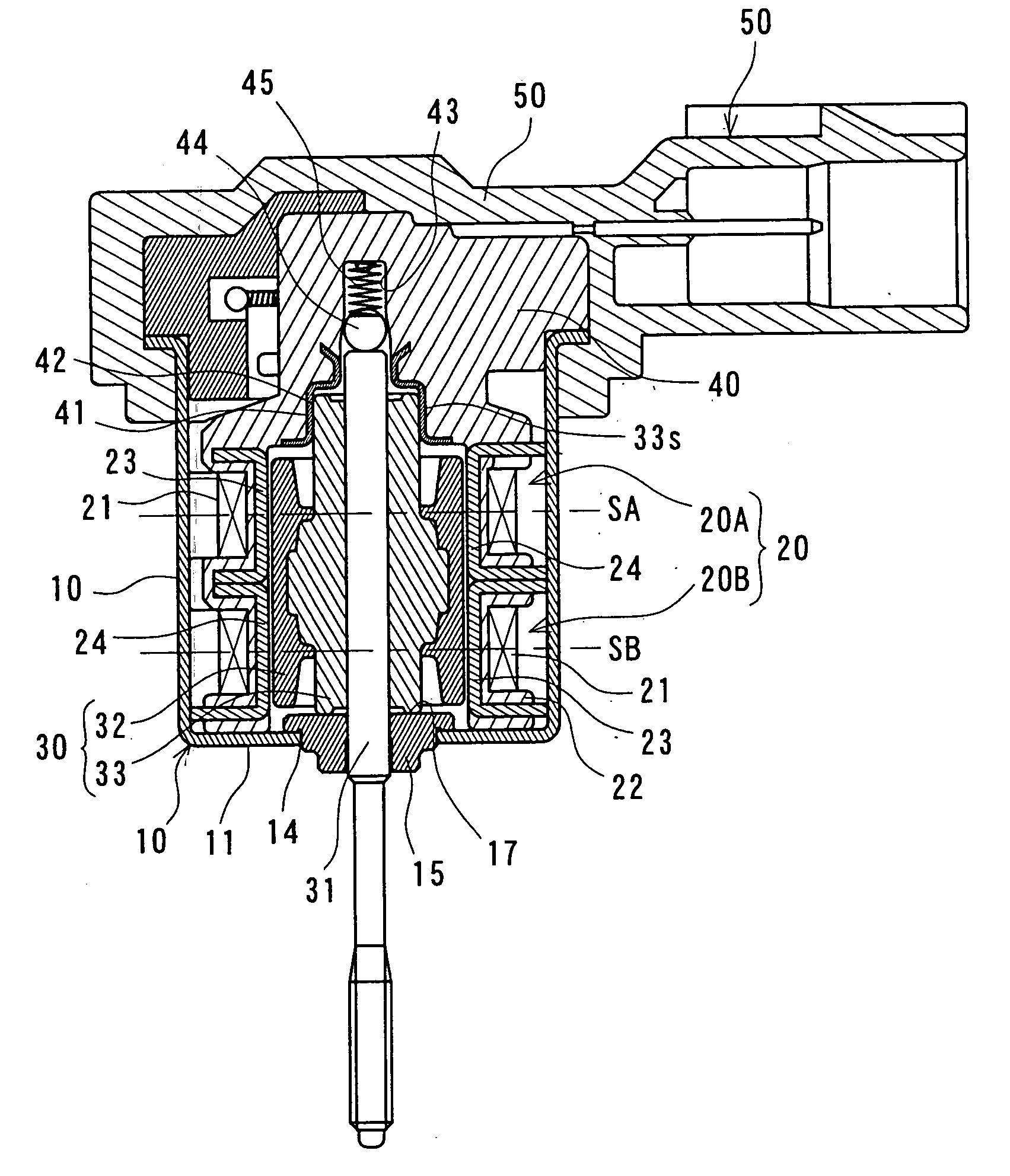
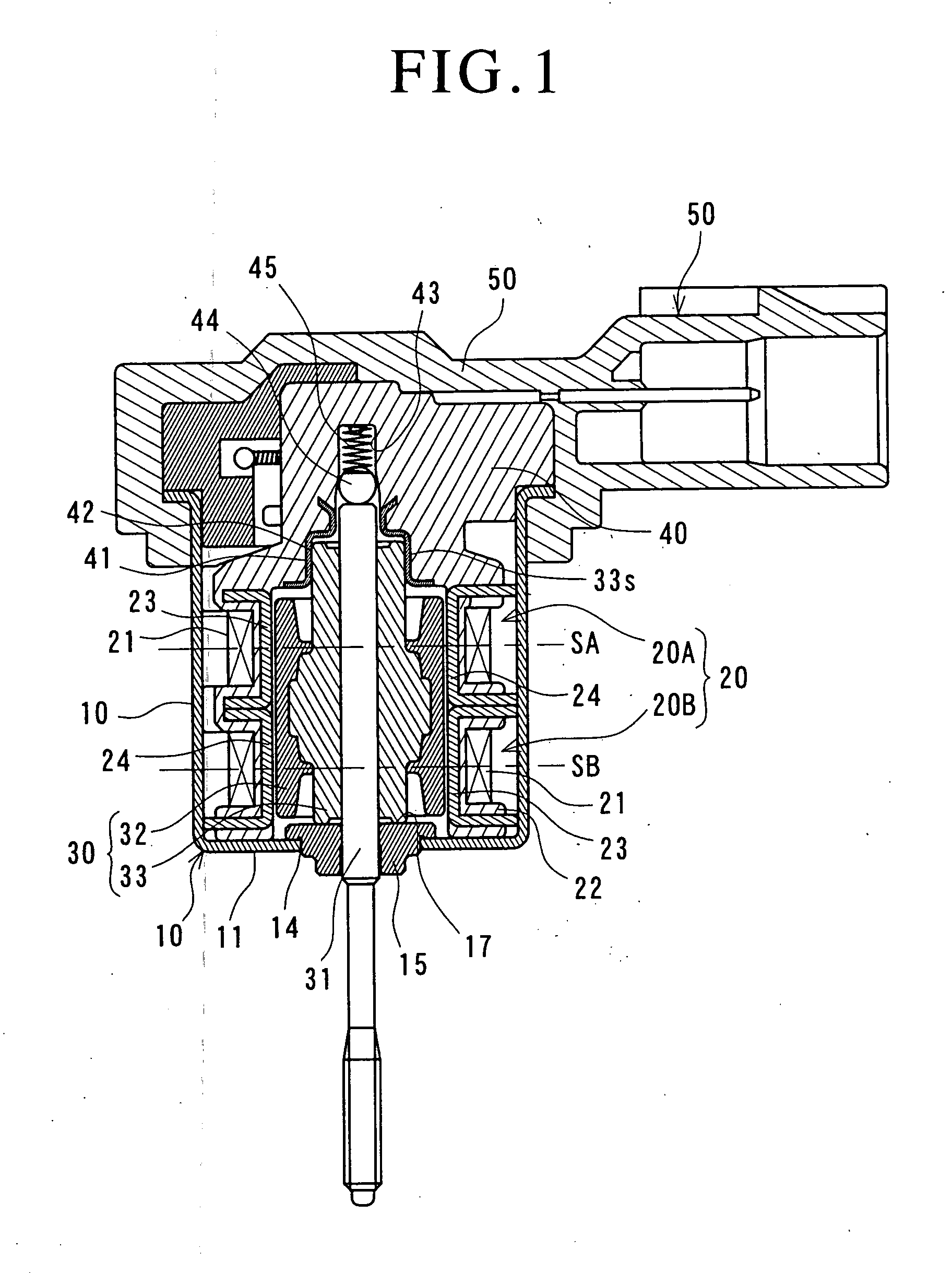
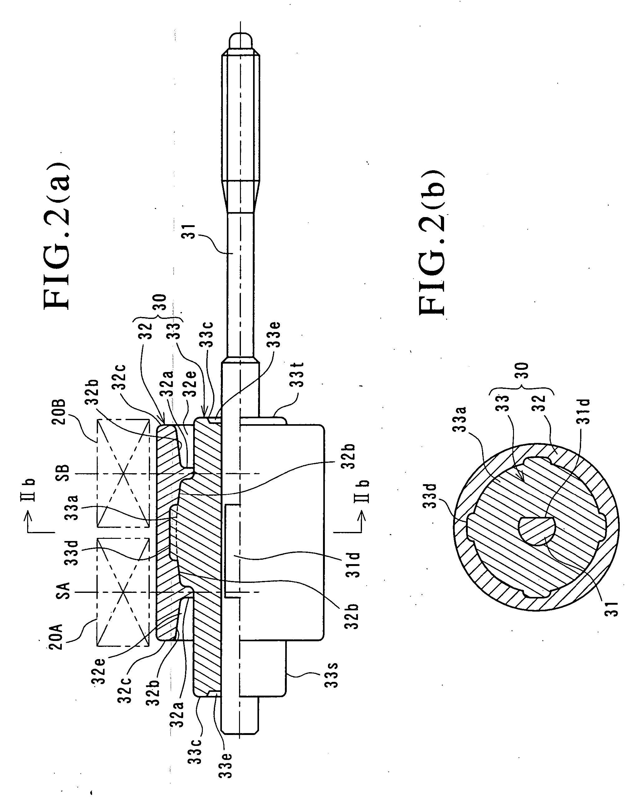
[0040]FIG. 1 is a sectional view showing an entire construction of a PM type stepping motor of the embodiment, FIGS. 2 (a) and 2 (b) are schematic diagrams of a rotor of the same stepping motor by taking out it, FIG. 2(a) is a side view showing an upper half part in section and FIG. 2(b) is a sectional view taken along the arrows IIb to IIb in FIG. 2(a).

[0041] A stepping motor is generally a device which converts an electric pulse signal into a step operation of mechanical interruption, and the PM type stepping motor shown here is constructed to synchronously rotate a rotor magnet which is magnetized in a circumferential direction to form multipoles by switching an electric current passed through a stator coil.

[0042] The stepping motor is constituted of a motor case 10 made of magnetic metal (for example, iron), a stator unit 20 including stators 20A and 20B of two phases t...


PUM


Abstract

A stepping motor which is capable of obtaining desired driving torque without sacrificing magnetic properties of a magnet with respect to a stator, reducing inertia mass of a rotor by decreasing a use amount of a magnet material, and thereby, can enhance driving performance including control responsiveness is provided. In a stepping motor in which a plurality of stators (20A, 20B) around which coils (21) are wound are placed in an axial direction of a motor shaft (31), a rotor (30) is rotatably provided with a space at inner periphery sides of these stators (20A, 20B), the motor shaft (31) is placed in a center of the rotor (30), and the rotor (30) includes a rotor body (33) placed at an outer periphery of the motor shaft and a cylindrical magnet (32) integrally provided on an outer periphery of the rotor body and magnetized to form multipoles in a circumferential direction, the stepping motor is characterized in that the cylindrical magnet (32) has at least its inner peripheral surface bulged inward in a diameter direction so that a portion corresponding to a central portion in the above described axial direction of each of the coils (21) becomes thicker than the other portions.

Description

TECHNICAL FIELD [0001] The present invention relates to a PM type stepping motor which has a plurality of stators in an axial direction of a motor shaft and is rotatably provided with a rotor including a magnet inside these stators. BACKGROUND ART [0002] As one type of a stepping motor, a PM type (Permanent Magnet Type) stepping motor is widely known. The PM type stepping motor is the one in which a magnet (permanent magnet) with magnetic poles placed in a circumferential direction is placed on an outer periphery of a rotor, and a stator including a driving coil is disposed around the magnet and, in general, stators of two phases are disposed to be aligned in a motor axial direction. [0003]FIG. 3 shows a conventional PM type stepping motor of this kind seen in Patent Document 1 described below. [0004] The stepping motor is constructed roughly by a cylindrical rotor 52 integrally provided with a motor shaft 51 in a center, a stator unit 53 placed at an outer periphery of the rotor 52...

Claims


Application Information

Patent Timeline
IPC IPC(8): H02K37/12H02K1/04
CPCH02K37/14H02K1/2733
Inventor OHKAWA, TAKANORIIDA, TAKASHIKODAIRA, OSAMU
Owner MITSUBISHI MATERIALS CMI CORP
Why Eureka
Try Eureka