Sensor and Disturbance Measurement Method Using the Same

Inactive Publication Date: 2008-04-10
SUMITOMO ELECTRIC IND LTD
View PDF12 Cites 59 Cited by
  • Summary
  • Abstract
  • Description
  • Claims
  • Application Information

AI Technical Summary

Benefits of technology

[0036] In accordance with the sensor and disturbance detection method according to the present invention, accurate temperature measurements can be performed within a wider temperature range including a low-temperature region of below 200 K, and disturbance types

Problems solved by technology

However, the problem associated with the measurement method using such a strain gage is that

Method used


Image

  • Sensor and Disturbance Measurement Method Using the Same
  • Sensor and Disturbance Measurement Method Using the Same
  • Sensor and Disturbance Measurement Method Using the Same

Examples


first embodiment

OF SENSOR

[0067] A sensor according to the first embodiment that comprises the optical fiber cable 10 having the above-described structure as a disturbance detection probe will be explained below. FIG. 5 shows the configuration of the first embodiment of the sensor according to the present invention. The temperature measurements employed with the sensor according to the first embodiment will be explained below in greater detail. A sensor 1 according to the first embodiment shown in FIG. 5 comprises the optical fiber cable 10 employed as a sensor section, a BOTDR (Brillouin Optical Time Domain Reflectometry) device 13, and a temperature analyzing section 14 (analyzing means) and serves to measure the temperature of an object to be measured 5. As described above, the optical fiber cable comprises optical fibers 12A, 12B, and these optical fibers 12A, 12B have core sections of waveguides of two types having different Brillouin scattering characteristics.

[0068] The BOTDR device 13 compr...

second embodiment

OF SENSOR

[0096] The sensor 1 according to the above-described first embodiment and modification example and the disturbance measurement method using the sensor are used for measuring only the temperature of the object to be measured 5, whereas in the sensor according to the second embodiment and the disturbance measurement method using such as a sensor, the temperature and strain are measured by using the temperature dependency of spectral width line and strain dependency of frequency shift that serve as parameters defining the Brillouin spectrum. As shown in FIG. 8, the sensor 2 according to the second embodiment comprises an optical fiber cable 10 that is a disturbance detection probe, a BOTDR device 13, a temperature analyzing section 14, and also a strain analyzing section 21.

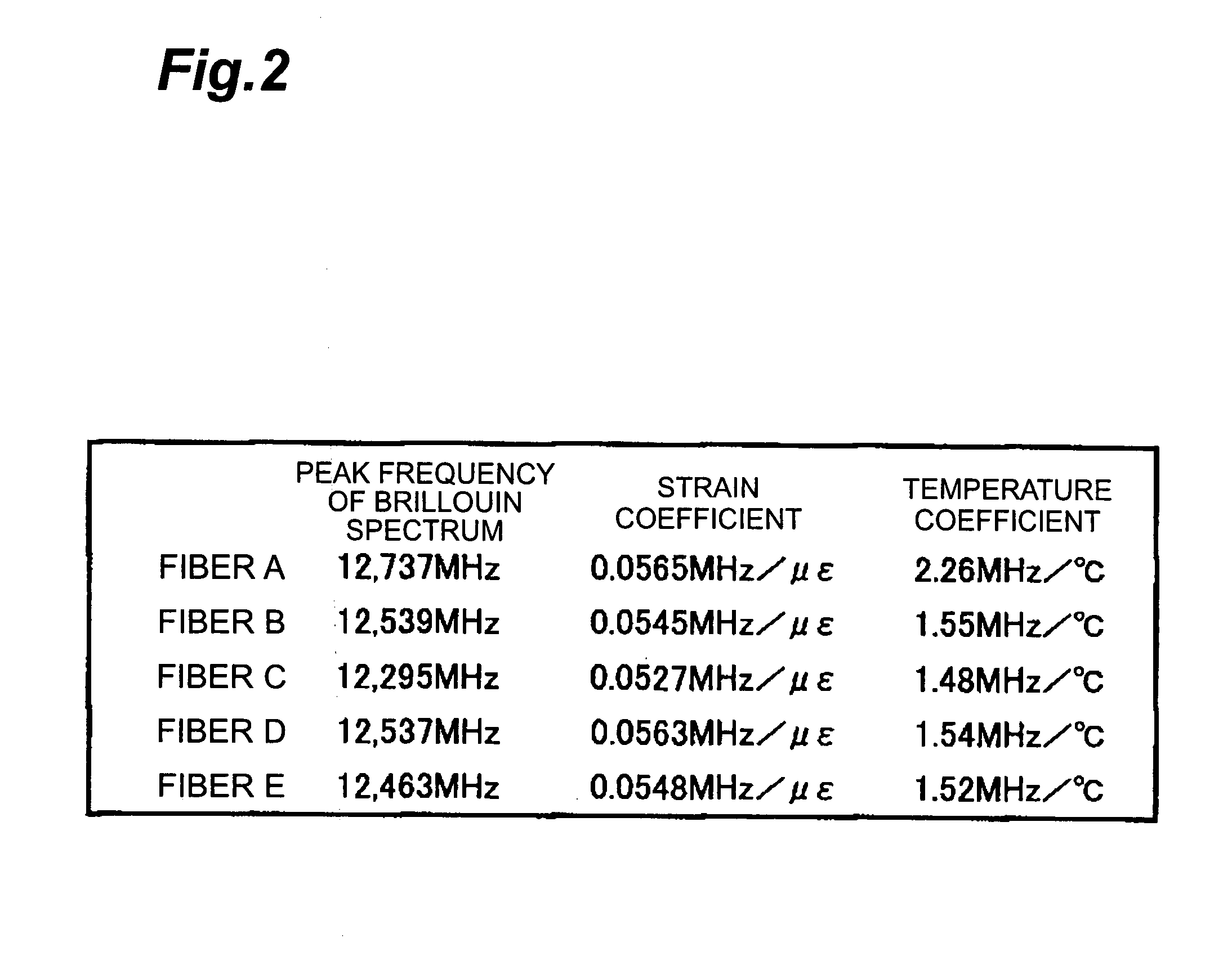
[0097] As described above, a plurality of optical fibers 12A, 12B included in the optical fiber cable 10 have Brillouin spectra that differ from one another in the temperature dependency of frequency shift...

third embodiment

OF SENSOR

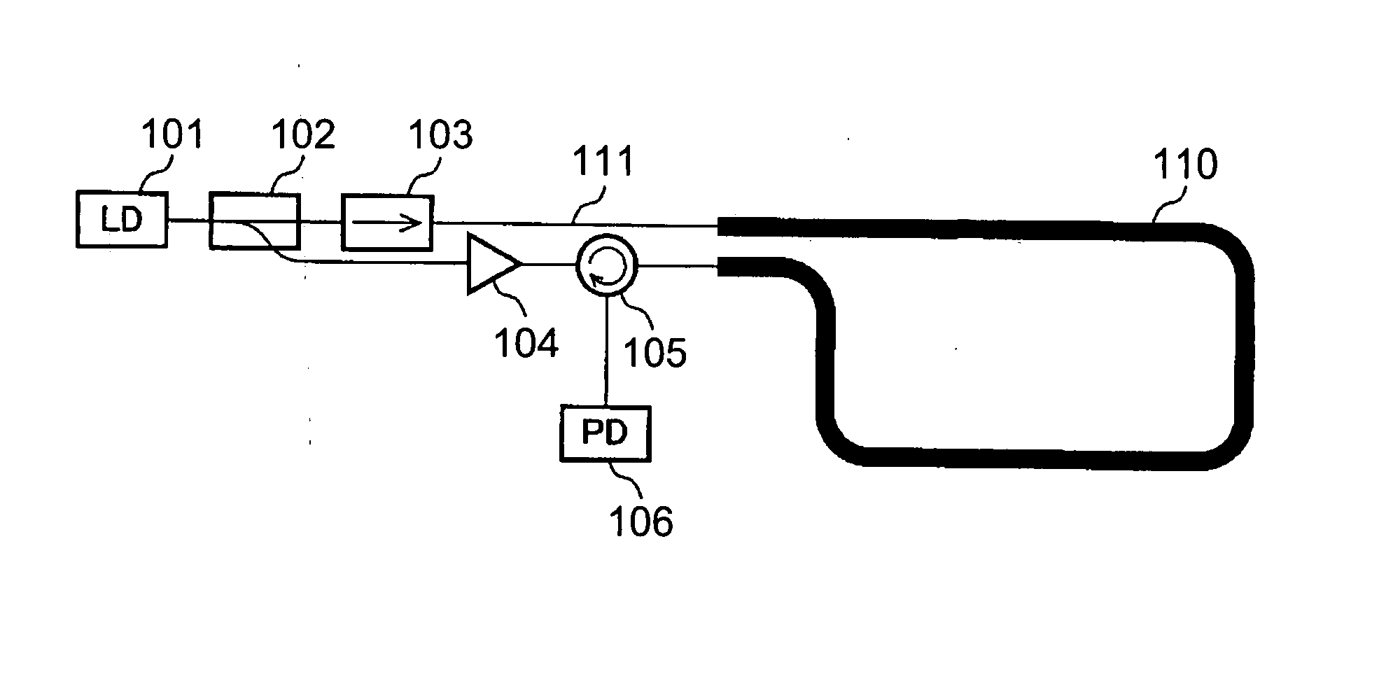
[0124] As described above, not only the disturbance measurements based on the BOTDR method, but a variety of other measurement methods can be implemented in the sensor according to the present invention. A BOCDA-type sensor will be explained below as the third embodiment of the sensor according to the present invention. FIG. 14 shows a configuration of the third embodiment of the sensor according to the present invention. The sensor 3 according to the third embodiment shown in FIG. 14 comprises a LD 15 that is a light source, a coupler 62 that divides the light signal equally into two parts, an isolator 63 through which the light can pass in one direction but cannot pass in the opposite direction, an amplifier 64 that amplifies the light signals, a circulator 65 having three ports and serving for coupling to one port that is adjacent to another port, a PD 16 (detecting section), which is a light-receiving element, an analyzing section 61 that analyzes a disturbance such as ...


PUM


Abstract

The present invention relates to a sensor or the like having a structure that enables accurate temperature measurement in a wide temperature range including a low-temperature region and is suitable for independently and accurately determining temperature variations and strains appearing in an object to be measured. The sensor comprises a laser light source, a sensor section that has a plurality of waveguides transmitting a laser light from the laser light source therethrough, a detecting section, and an analyzing section. The detecting section detects a plurality of Brillouin spectra obtained from the sensor section. The analyzing section determines at least one measurement value of a temperature in the sensor section and a strain generated in the sensor section, based on fluctuations of parameters defining the respective detected Brillouin spectra. In particular, the sensor section has a structure such that the variation of the Brillouin spectrum in response to a disturbance differs between the waveguides. Thus, by simultaneously monitoring the Brillouin spectra that varying a different manner in a plurality of waveguides, it is possible not only to measure accurately the temperature in a wide temperature range including a low-temperature region, but also to make distinction between the strain and temperature.

Description

RELATED APPLICATIONS [0001] This application is a national phase of PCT / JP2006 / 319451 filed Sep. 29, 2006, which claims priority from Japanese Application No. 2005-283315 filed Sep. 29, 2005 and Japanese Application No. 2005-316872 filed Oct. 31, 2005, the disclosures of which Applications are incorporated by reference herein. The benefit of the filing and priority dates of the International and Japanese Applications is respectfully requested.TECHNICAL FIELD [0002] The present invention relates to a sensor for measuring at least one of temperature (or temperature distribution) of a waveguide and strain (or strain, distribution) occurring in a waveguide by using the waveguide through which a laser light, as a probe for detecting disturbances such as external forces or heat and for monitoring the spectrum of a Brillouin scattering light (hereinbelow called “Brillouin spectrum”) outputted from the waveguide, propagates, and to a disturbance measurement method using such a sensor. BACKG...

Claims


Application Information

Patent Timeline
IPC IPC(8): G01K3/00
CPCG01B11/18G01K11/32G01D5/35348G01M11/083G01L1/243G01B11/16G01D5/353G01K11/00G01K11/12
Inventor YAMAMOTO, YOSHINORISAKABE, ITARUSASAOKA, EISUKETANJI, HISASHI
Owner SUMITOMO ELECTRIC IND LTD
Why Eureka
Try Eureka