Galley cooling heat sink through water system

a heat sink and gallon technology, applied in the direction of transportation and packaging, lighting and heating equipment, energy-saving board measures, etc., can solve the problems of noise and heat dissipation, heat removed from the cooling compartment of the refrigerator is expelled directly to air, and space and weight limitations need to be considered, so as to achieve the effect of more efficient heat transportation

Active Publication Date: 2008-04-17
MAG AEROSPACE IND INC
View PDF40 Cites 43 Cited by
  • Summary
  • Abstract
  • Description
  • Claims
  • Application Information

AI Technical Summary

Problems solved by technology

Aircraft, as well as other transport vehicles, present unique challenges to cooling these food carts or other areas that need to stay refrigerated or cooled.
For example, space and weight limitations need to be considered, as well as noise and heat dissipation issues.
Refrigerators are not used for the majority of aircraft food cooling because of the great amount of space and labor that would be required to load and unload the food from between the carts and refrigerators on each flight.
Another problem with refrigerators is that heat removed from the cooling compartment of the refrigerator is expelled directly to air in the galley.
This can cause excess work for the air conditioning system of the aircraft to remove this heat.
However, dry ice is short-lasting and thus provides insufficient refrigeration for longer trips.
Other downsides are that dry ice is a recurring cost (it has to be re-loaded before each trip or flight) that requires extra manpower / labor to load, it adds to the weight of the vehicle, and it can cause safety concerns due to its very low temperature.
Split systems can be unreliable, and if they leak, the leak is at a joint or seal that needs to be repaired on the aircraft itself (i.e., it is not a line replaceable unit (LRU) that can be taken off the plane and replaced, while the defective unit is repaired elsewhere).
Service can be very costly because the aircraft needs to be grounded for at least about eight hours.
Both of the fluids used in chilled liquid systems are inferior to water as a heat transfer medium due their higher viscosity and lower specific heat.
Additionally, Galden is approximately $400 per gallon, which can greatly increase the cost of using such a system.
Another disadvantage of chilled liquid systems is that they involve a fairly complex series of pumps and tubing.
Other drawbacks of a chilled liquid system include fluid leakage, low reliability due to its complexity, and perhaps most importantly, its weight, an issue of primary concern in aircrafts.
Additionally, chilled liquid systems have historically been failure prone, and since they are an interconnected system, if one component fails, it is likely that most or all of the refrigeration is lost on the aircraft.
This makes maintenance more complicated because the entire system must be checked and adjusted whenever any one component is replaced.
As discussed above, any maintenance that must be conducted on an aircraft system (versus on a part that can be removed, replaced, and repaired in a workshop off-site) is very costly.
By contrast, typical air chiller designs expel heat from the chiller near (or in or above) the galleys and create excess heat in these areas, resulting in undue strain on the air conditioning system or requiring complicated ducting to remove the heat.
If a duct seal is not installed correctly, or degrades over time, the loss of a small amount of chilled air makes the system slightly less efficient, but does not render the system inoperable.
One primary drawback of air chiller units, however, is that heat is rejected near the point at which they are installed.
This can limit installation design because the units must be installed near the chilled compartments, yet they dissipate heat in the same area.
The space near a galley is normally filled with other equipment and is not ideal for dissipating heat.
The dissipated heat puts an additional load on the ECS (Environmental Control System) equipment, which causes inefficiency.
Additionally, the galleys are near passengers, and noise from the air chiller fan and compressor can cause passenger complaints.
Accordingly, the airflow used for the discharge heat must often be ducted some distance away from a chiller for heat and / or noise control, which puts an additional load on the chiller fan and requires additional space in the aircraft for the ducting.
It can thus be challenging to locate this ducting within the aircraft system.

Method used


Image

  • Galley cooling heat sink through water system
  • Galley cooling heat sink through water system
  • Galley cooling heat sink through water system

Examples


Embodiment Construction

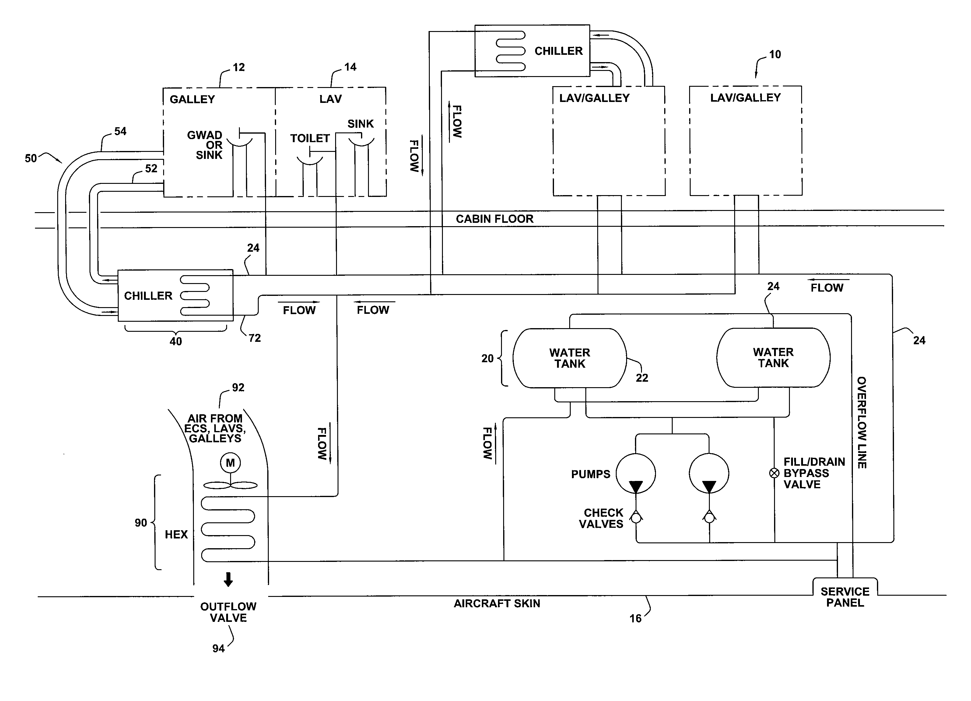
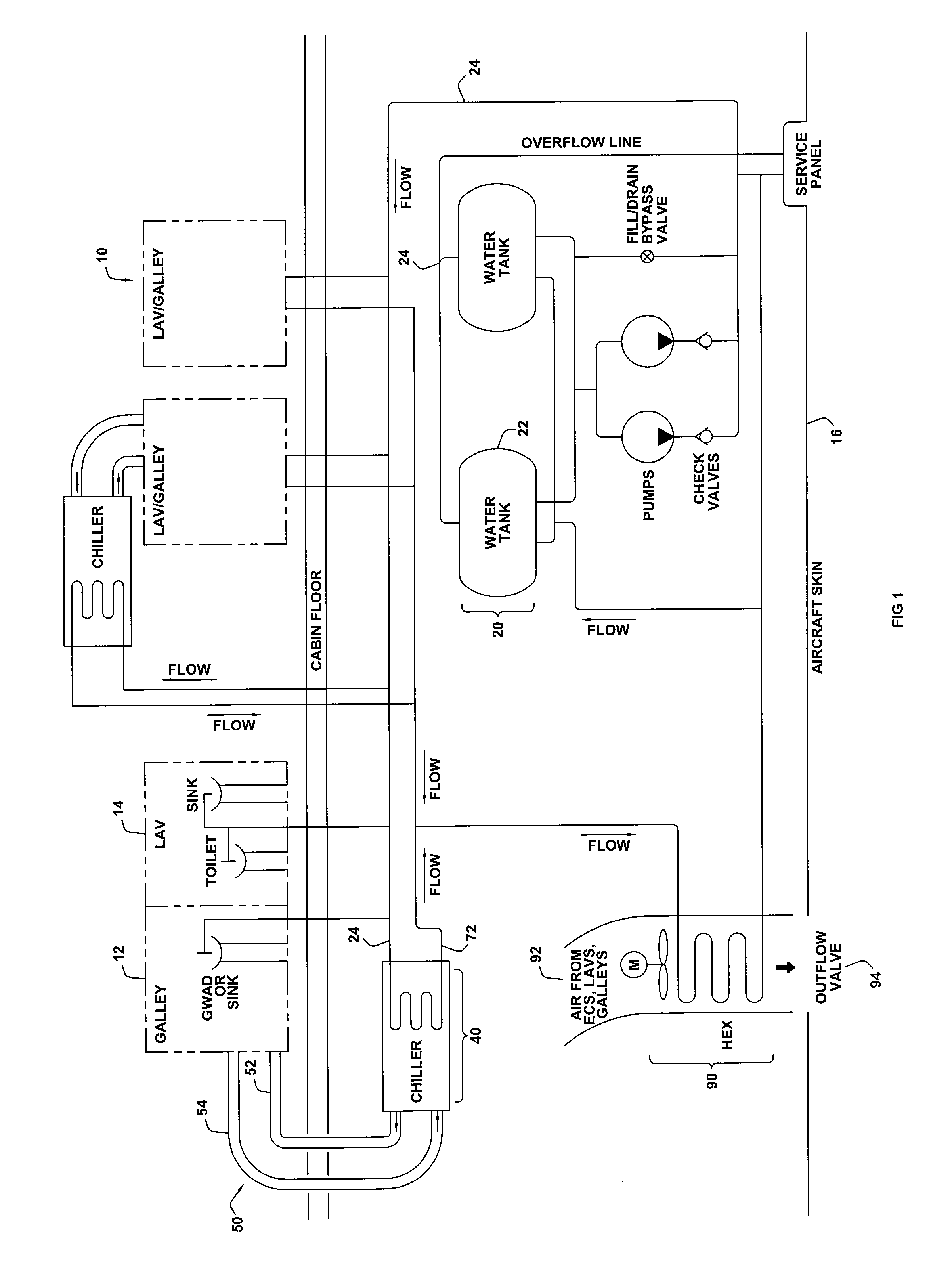
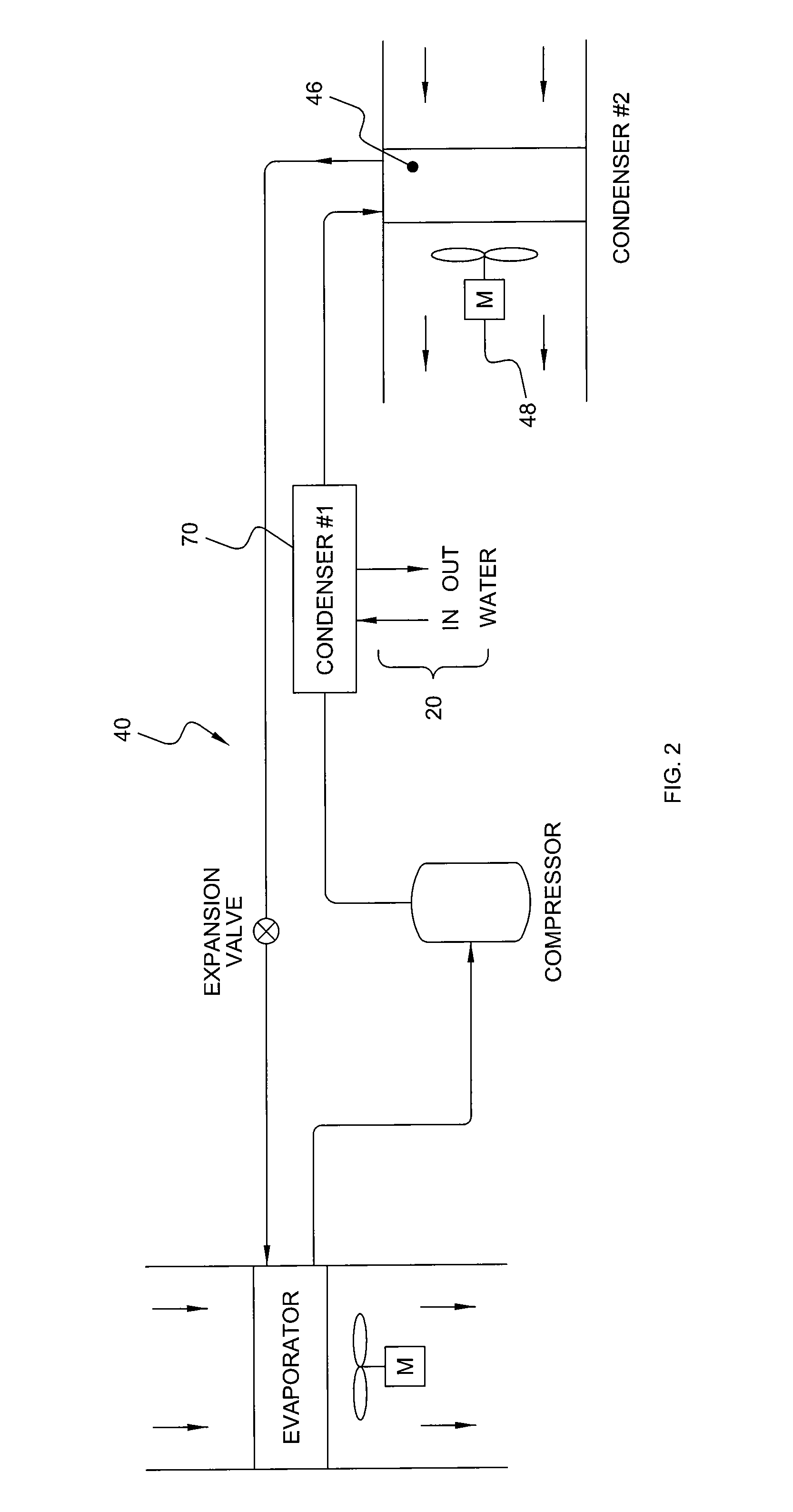
[0039] Embodiments of the present invention relate to systems and methods for cooling various compartments, systems, and devices of transport vehicles. For example, food products to be served to passengers onboard aircraft are traditionally kept cool in compartments through chilled recirculated air. Other devices, such as electronics, avionics, or other systems that generate heat, may also need to be cooled. For ease of reference, this invention will be described with respect to aircraft galley refrigeration systems for cooling food products in food carts or compartments, but it should be understood that it is equally applicable to other transport vehicles, such as large passenger buses, watercraft, etc., and may be used to cool systems other than food compartments, such as power electronic units, avionics, in-flight entertainment units, and any other heat-generating equipment that may need to be cooled.

[0040] The designs described in this application generally use a potable water ...


PUM


Abstract

There is provided systems and methods for transporting heat away from galley refrigeration equipment or other heat-generating systems such as avionics, power electronics, or in-flight entertainment units, via a potable water system. The potable water system transports heat more effectively and more efficiently than other systems used to date.

Description

[0001] This application claims the benefit of U.S. Provisional Application Ser. No. 60 / 819,562, filed Jul. 10, 2006 titled “Aircraft Galley Refrigeration Cooling Heat Sink through Water System,” U.S. Provisional Application Ser. No. 60 / 832,208, filed Jul. 20, 2006 titled “Aircraft Heat Management System,” and U.S. Provisional Application Ser. No. 60 / 906,358, filed Mar. 12, 2007 titled “Chiller and Refrigerant-to-Water Heat Exchanger Design,” the entire contents of each of which are hereby incorporated by reference.FIELD OF THE INVENTION [0002] Embodiments of the present invention generally relate to systems and methods for transporting heat away from galley refrigeration equipment or other heat-generating systems such as avionics, power electronics, or in-flight entertainment units, via a potable water system. BACKGROUND OF THE INVENTION [0003] Food products for consumption onboard commercial aircraft are located in carts and compartments within the galley area of the aircraft. Thes...

Claims


Application Information

Patent Timeline
Patent Type & Authority Applications(United States)
IPC IPC(8): F25B1/00
CPCB64D11/02B64D11/04B64D13/06B64D2013/0614B60H1/32B64D2013/0674Y02T50/44Y02T50/46Y02T50/56B64D2013/0629Y02T50/50Y02T50/40
Inventor REED, FRED M.LEE, THOMAS M.
Owner MAG AEROSPACE IND INC
Why Eureka
Try Eureka