Refrigerant cycle device with ejector

a refrigerant cycle and ejector technology, which is applied in the direction of manufacturing tools, lighting and heating equipment, furniture, etc., can solve the problems of inability to enhance the effect of cycle efficiency improvement, and achieve the effects of reducing manufacturing costs, increasing refrigeration capacity of cycles, and small dryness

Inactive Publication Date: 2008-04-17
DENSO CORP
View PDF6 Cites 21 Cited by
  • Summary
  • Abstract
  • Description
  • Claims
  • Application Information

AI Technical Summary

Benefits of technology

[0017] In the above refrigerant cycle device, an area of a heat radiation portion of the first radiator for allowing the refrigerant to radiate heat is smaller than that of a heat radiation portion of the second radiator for allowing the refrigerant to radiate heat. Accordingly, it can easily obtain the structure in which the amount of heat radiated from the refrigerant in the first radiator is smaller than that in the second radiator.
[0018] Alternatively, the second radiator is a heat exchanger for exchanging heat between the refrigerant passing through an inside thereof and air passing through an outside thereof, and the first radiator is a heat exchanger for exchanging heat between the refrigerant passing through an inside thereof and the air after being heat-exchanged in the second radiator. In this case, because a difference in temperature between the refrigerant and air in the first radiator is smaller than that between the refrigerant and air in the second radiator, it can easily achieve the structure in which the amount of heat radiated from the refrigerant in the first radiator is smaller than that in the second radiator.
[0019] The refrigerant cycle device may be provided with an outflow-side evaporator for evaporating the refrigerant flowing out of the diffuser portion. Thus, the refrigerant can exhibit the heat absorption effect not only in the suction-side evaporator, but also in the outflow-side evaporator.
[0020] The refrigerant cycle device may be further provided with a vapor/liquid separator for separating the refrigerant on a downstream side of the diffuser portion into vapor-phase refrigerant and liquid-phase refrigerant to allow the vapor-phase refrigerant to flow to a sucti...

Problems solved by technology

Therefore, it is impossible to enhance the effect of improvement in the cycle eff...

Method used


Image

  • Refrigerant cycle device with ejector
  • Refrigerant cycle device with ejector
  • Refrigerant cycle device with ejector

Examples


first embodiment

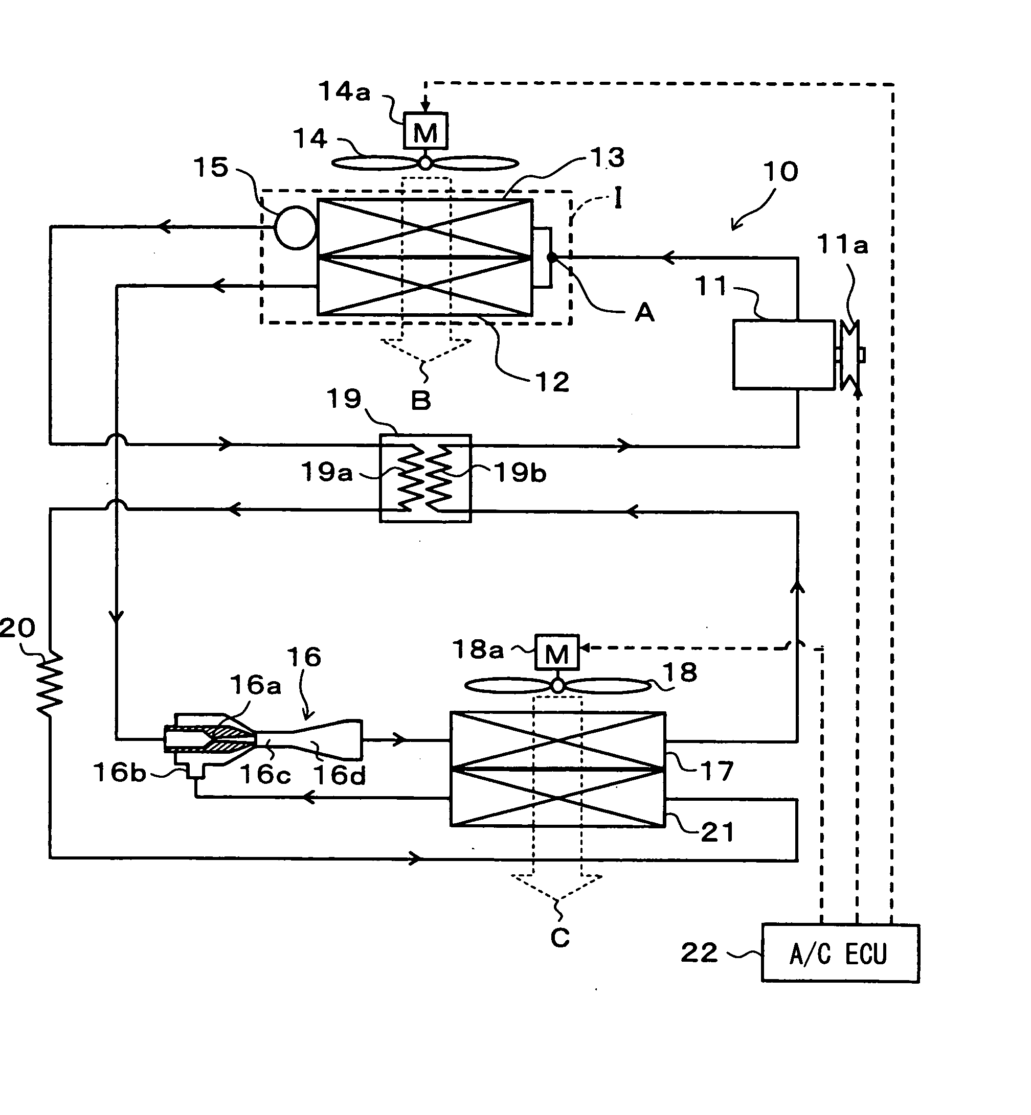
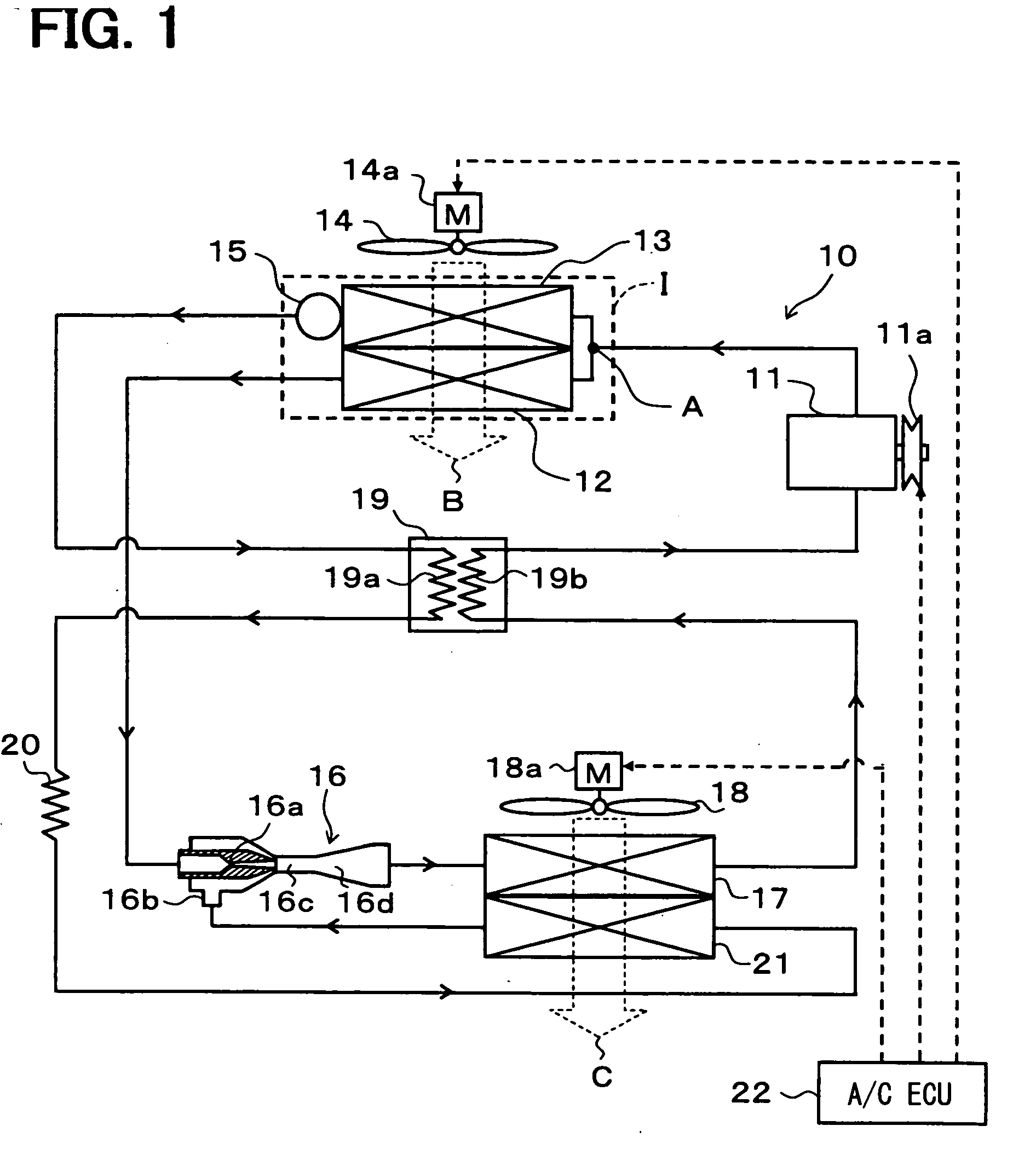
[0029] A first embodiment of the invention will be described below with reference to FIGS. 1 to 3. FIG. 1 is a diagram showing an example of an entire structure of a refrigerant cycle device 10 according to the invention, which is applied to an air conditioner for a vehicle. In the refrigerant cycle device 10 of this embodiment, a compressor 11 for sucking and compressing the refrigerant is rotatably driven by an engine for vehicle running (not shown) via an electromagnetic clutch 11a, a belt, and the like.

[0030] The compressor 11 may be either a variable displacement compressor for being capable of adjusting a refrigerant discharge capacity by a change in discharge capacity. Alternatively, the compressor 11 may be a fixed displacement compressor for adjusting a refrigerant discharge capacity by changing an operating efficiency of a compressor operation by intermittent connection of the electromagnetic clutch 11a. The use of an electric compressor as the compressor 11 can adjust th...

second embodiment

[0090] In the above first embodiment, the receiver 15 is disposed on the downstream side of the second radiator 14. However, in a second embodiment, as shown in FIG. 4, the receiver 15 is removed, and an accumulator 23 is disposed on the downstream side of the outflow-side evaporator 17. The accumulator 23 is a vapor / liquid separator for separating the low-pressure refrigerant on the downstream side of the outflow-side evaporator 17 into the vapor-phase refrigerant and liquid-phase refrigerant to store therein the liquid-phase refrigerant.

[0091] The accumulator 23 has a tank-like shape, and is adapted to separate the refrigerant into the liquid and vapor phases by a difference in density between these phases. The accumulator 23 allows the vapor-phase refrigerant from a vapor-phase refrigerant outlet provided in an upper portion thereof to flow into the suction side of the compressor 11, and the liquid-phase refrigerant from a liquid-phase refrigerant outlet provided at the bottom t...

third embodiment

[0104]FIG. 6 is a diagram of an entire structure of a refrigerant cycle device according to a third embodiment of the invention. The third embodiment differs from the first embodiment in that the outflow-side evaporator 17 is not provided. The structures of other elements of this embodiment are the same as those of the first embodiment.

[0105] Also in the refrigerant cycle of the third embodiment, the branch portion A is disposed on the upstream side of the first radiator 12 and the second radiator 13, so that the amount of heat radiated from the refrigerant in the first radiator 12 is smaller than that in the second radiator 13. Thus, the refrigerant cycle of this embodiment can increase the enthalpy of refrigerant on the inlet side of the nozzle portion 16a as compared to the refrigerant cycle of the comparison example in which the branch portion A is disposed on the downstream side of the second radiator 13 and on the upstream side of the nozzle portion 16a.

[0106] As a result, l...


PUM

PropertyMeasurementUnit
Areaaaaaaaaaaa
Heataaaaaaaaaa

Abstract

A refrigerant cycle device includes a branch portion for branching a flow of refrigerant discharged from a compressor, a first radiator for radiating one high-temperature and high-pressure refrigerant branched at the branch portion, an ejector including a nozzle portion for decompressing refrigerant on a downstream side of the first radiator, a second radiator for radiating the other high-temperature and high-pressure refrigerant branched at the branch portion, a throttle device for decompressing refrigerant on a downstream side of the second radiator, and a suction side evaporator for evaporating refrigerant downstream of the throttle device and for allowing the refrigerant to flow to an upstream side of a refrigerant suction port of the ejector. Furthermore, the first and second radiators are disposed downstream of the branch portion such that a heat radiation amount of refrigerant in the first radiator is smaller than that in the second radiator.

Description

CROSS REFERENCE TO RELATED APPLICATION [0001] This application is based on Japanese Patent Application No. 2006-219478 filed on Aug. 11, 2006, the contents of which are incorporated herein by reference in its entirety. FIELD OF THE INVENTION [0002] The present invention relates to a refrigerant cycle device having an ejector. BACKGROUND OF THE INVENTION [0003] JP-A-2005-308380 conventionally discloses a refrigerant cycle device in which a branch portion for branching the flow of refrigerant is disposed on the upstream side of a nozzle portion of an ejector and on the downstream side of a radiator for radiating heat from the refrigerant discharged from a compressor. One of the refrigerants branched flows into the nozzle portion side, while the other refrigerant flows into a refrigerant suction port of the ejector. [0004] In this refrigerant cycle device, a first evaporator (an outflow-side evaporator) is disposed on the downstream side of a diffuser portion of the ejector, and a thro...

Claims


Application Information

Patent Timeline
IPC IPC(8): F25B1/06F25B39/02
CPCF25B5/04F25B6/02F25B2341/0661F25B41/00F25B2341/0012F25B40/00B60H2001/3298F25B41/385
Inventor OSHITANI, HIROSHITAKEUCHI, HIROTSUGUTAKANO, YOSHIAKIGOCHO, MIKA
Owner DENSO CORP
Why Eureka
Try Eureka