
Engine and motorcycle

Inactive Publication Date: 2008-04-17
KAWASAKI HEAVY IND LTD
View PDF14 Cites 5 Cited by
  • Summary
  • Abstract
  • Description
  • Claims
  • Application Information

AI Technical Summary

Benefits of technology

[0008] The present invention addresses the above-described conditions. An object of the present invention is to provide an overhead cam engine having a compact cylinder head block and a motorcycle that is equipped with the engine, thereby avoiding an increase in the width of the frame of the motorcycle.
[0011] The cylinder head block may be fastened to the cylinder block located thereunder by a bolt in a location below the driving power transmission mechanism. In such a configuration, since it is not necessary to provide bolt mounting positions outside the driving power transmission mechanism, the size of the cylinder head block, particularly in a forward and rearward direction, and its weight, can be reduced.
[0012] At least one of the driving power transmission mechanism and the camshaft drive system may have a valve timing adjusting mechanism. In such a configuration, the valve timing adjusting mechanism can be easily disposed.
[0016] In a state where the engine is mounted in the motorcycle, the second camshaft may be positioned forward relative to the first camshaft. In such a configuration, since the camshaft that is not attached with the camshaft drive system is positioned forward, i.e., in a space between the pair of tank rail frame members, the distance between the pair of tank rail frame members can be reduced.

Problems solved by technology

If the distance between the pair of tank rail frame members increases, then stiffness, in particular longitudinal stiffness and torsional stiffness of the entire frame of the motorcycle increases, but toughness of the entire frame decreases, making it difficult for a rider to turn and steer the motorcycle.

Method used


Image

  • Engine and motorcycle
  • Engine and motorcycle
  • Engine and motorcycle

Examples


Embodiment Construction

[0031] Hereinafter, an engine according to an embodiment of the present invention, and a motorcycle equipped with the engine will be described with reference to the accompanying drawings.

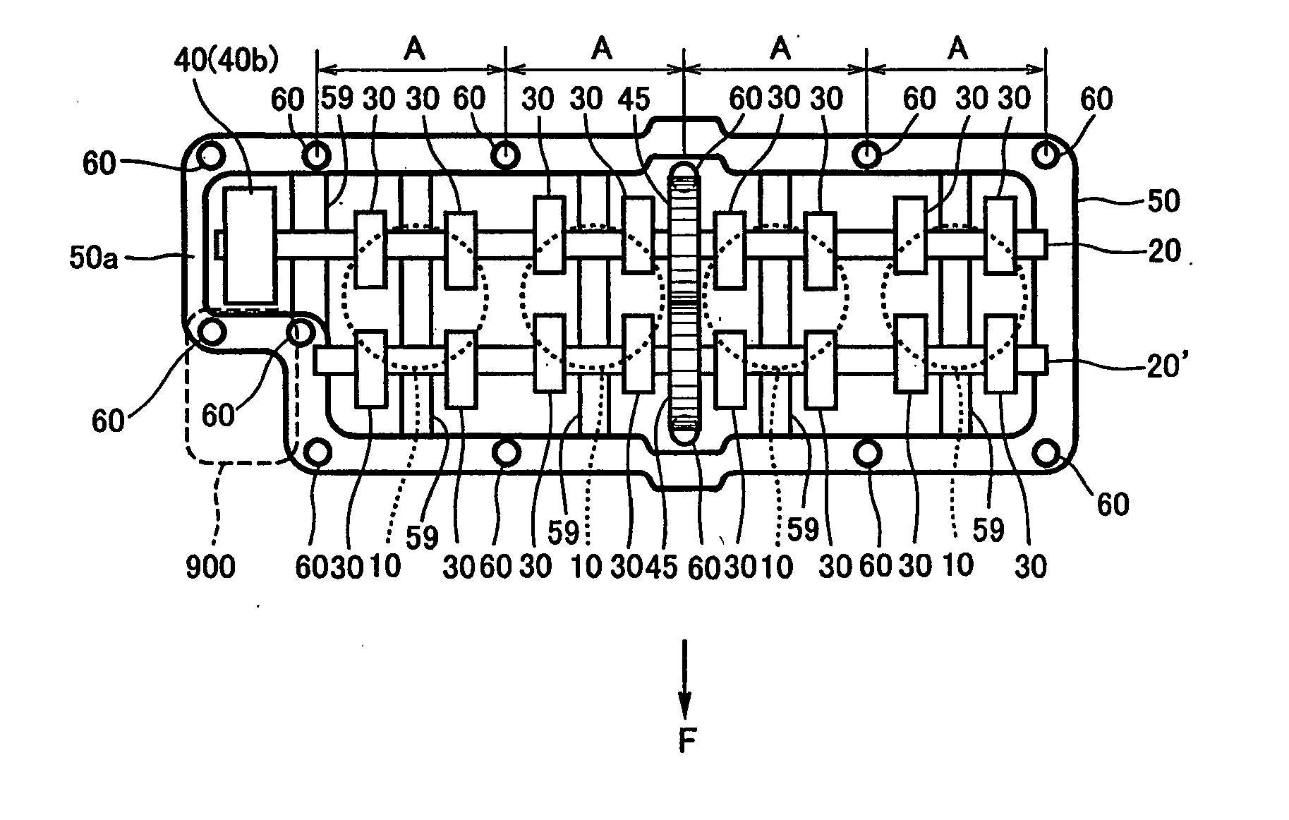
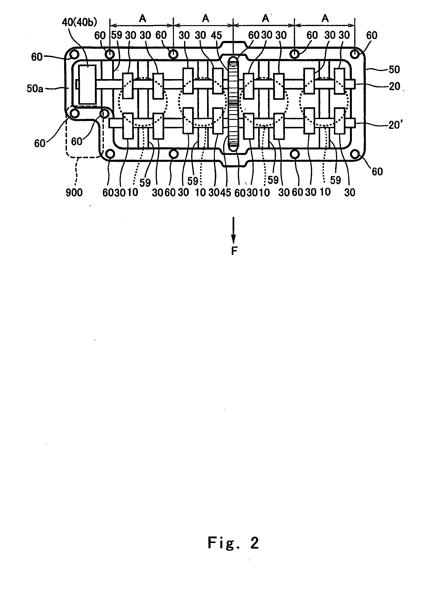
[0032]FIG. 2 is a plan view of a cylinder head block 50 of the engine according to an embodiment of the present invention. As shown in FIG. 2, the cylinder head block (hereinafter simply referred to as “head block”) 50 of the engine is applied to an in-line four-cylinder DOHC (double overhead camshaft) engine but may be suitably applied to other multi-cylinder DOHC engines.

[0033] In the embodiment, “F” indicates a forward direction of the motorcycle 100 (see FIG. 3) of the embodiment.

[0034] The head block 50 is provided with a first camshaft 20 and a second camshaft 20′ disposed to extend along a direction in which cylinders 10 are aligned, i.e., in the width direction of the head block 50. Each of the first and second camshafts 20 and 20′ has cams 30 for each cylinder 10. The cams 30 of one of t...


PUM


Abstract

A multiple-cylinder DOHC engine, including a cylinder head block, a first camshaft that is mounted on the cylinder head block and is configured to drive one of an intake valve and an exhaust valve mounted on the cylinder head block, a second camshaft that is mounted on the cylinder head block and is configured to drive the other one of an intake valve and an exhaust valve, a camshaft drive system that is mounted at an end portion of the first camshaft in an axial direction thereof and is configured to drive the first camshaft, and a driving power transmission mechanism that is disposed at a center portion of the first and second camshafts in the axial direction to transmit a driving power from the first camshaft to the second camshaft.

Description

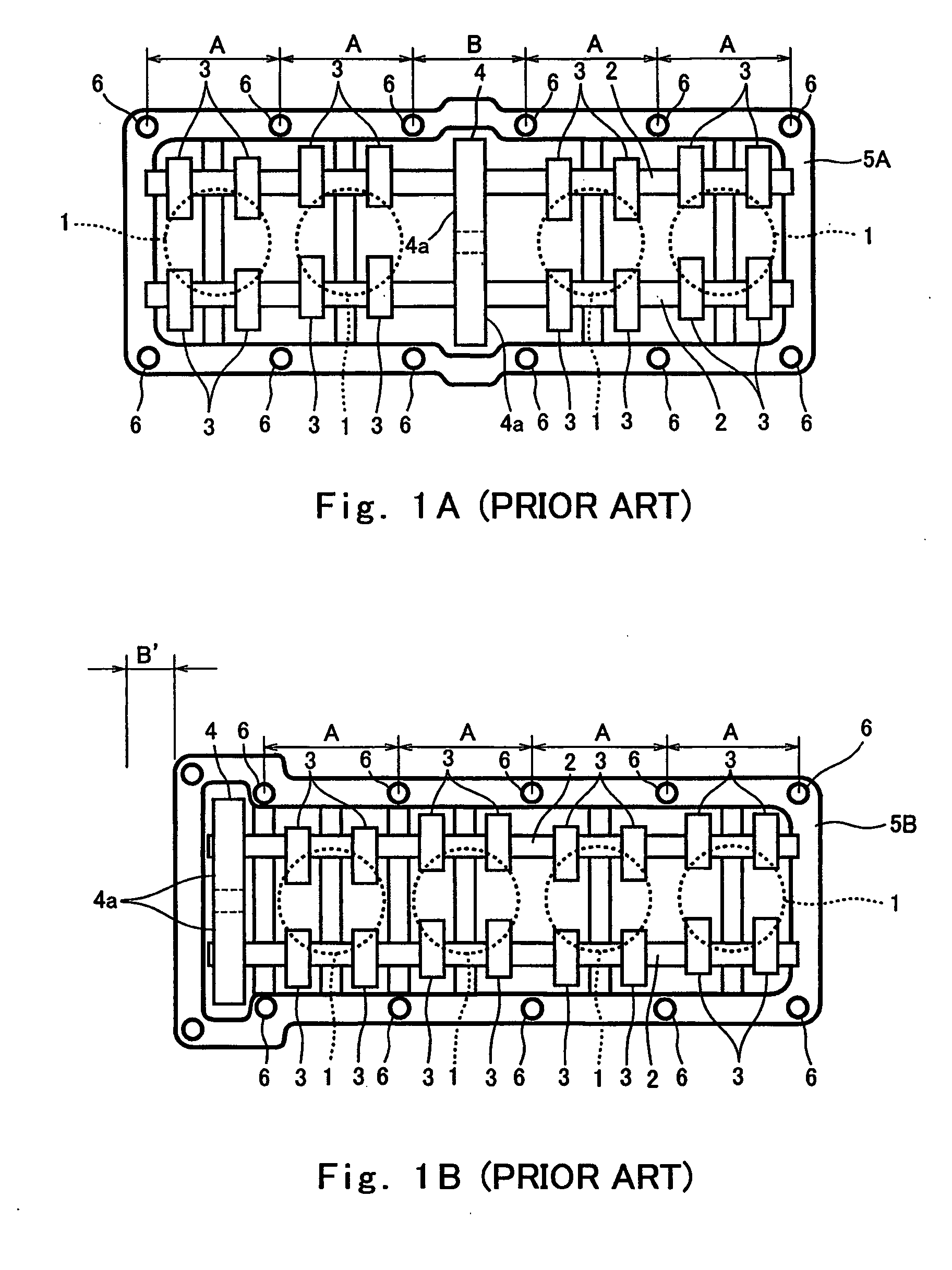
TECHNICAL FIELD [0001] The present invention relates to an overhead cam engine and a motorcycle equipped with the engine. BACKGROUND [0002] A center cam train structure for driving a camshaft which is used in, for example, an inline four-cylinder overhead cam engine or the like for a motorcycle, is disclosed in Japanese Laid-Open Patent Application Publication No. Sho. 60-243307. FIG. 1A is a plan view of a cylinder head block (simply referred to as a “head block”5A), having a conventional center cam train structure. The center cam train structure is configured in such a manner that a chain line unit 4 disposed at a center of four cylinders 1 (indicated by broken-line circles in FIG. 1A) aligned in the width direction of head block 5A drives two camshafts 2 that are provided with cams 3 and are respectively configured to drive an intake valve and an exhaust valve. [0003] It is necessary to fasten head block 5A to a cylinder block (not shown) located thereunder firmly by bolts 6 at o...

Claims


Application Information

Patent Timeline
IPC IPC(8): F01M3/00
CPCF01L1/022F01L1/024F01L1/026F01L1/053F01M11/02F01L2001/0537F01L2103/02F01M9/10F01L1/26F01L2303/02
Inventor MATSUDA, YOSHIMOTO
Owner KAWASAKI HEAVY IND LTD
Learn More