Roller cone drill bits with optimized bearing structures

a technology of bearing structure and which is applied in the direction of earth-moving drilling, drilling machine and method, and accessories, etc. it can solve the problems of high load on the associated bearing structure, high load applied to and high speed of the roller cone drill bit. achieve the effect of reducing the bearing load acting

Active Publication Date: 2008-04-17
HALLIBURTON ENERGY SERVICES INC
View PDF17 Cites 16 Cited by
  • Summary
  • Abstract
  • Description
  • Claims
  • Application Information

AI Technical Summary

Benefits of technology

[0012] Therefore, a need has arisen for a design method that accounts for variations in cutting structures of a rotary cone drill bit and provides bearing assemblies designed to optimize performance of the drill bit. A further need has arisen to reduce bearing load by optimally designing both cutting structures and bearing structures associated with a rotary cone drill bit.
[0013] In accordance with teachings of the present disclosure, a roller cone drill bit may be provided with optimally designed bearing structures to substantially reduce or eliminate problems associated with existing bearing structures and to increase the drilling life of associated bearings and seal assemblies. The roller cone drill bit may include a cone assembly with a distinct cutting structure rotatably mounted to a spindle via a bearing structure. Each cone assembly may have a minimal moment center located along a respective axis of rotation. The minimal moment center is defined by characteristics of the respective distinct cutting structure. Each bearing structure includes a respective geometric bearing center point based on the location of each bearing relative to the bearing axis of the spindle. The minimal moment center of the associated cone assembly may be designed to be proximate the geometric bearing center point to overcome problems associated with previous roller cone drill bits and methods of manufacturing and designing roller cone drill bits.
[0017] The present invention includes a number of technical benefits such as providing bearing structures with center points located proximate to a minimal moment center of an associated cone assembly. Minimizing any displacement between each center point and the associated minimal moment center allows each bearing structure to better support an associated cone assembly and reduces the bearing load acting on each cone assembly.
[0018] Designing each cutting structure to have a minimal moment center proximate the associated bearing center point reduces the effect of changes in cutting structures between each cone assembly of a rotary cone drill bit.

Problems solved by technology

Roller cone drill bits often operate at relatively low speeds with heavy load applied to the bit.
This produces a very high load on the associated bearing structures, increasing wear on the bearing structure and directly impacting the life of the bearing.
Therefore, design of bearing structure is often a key issue for roller cone bit manufacturers.

Method used


Image

  • Roller cone drill bits with optimized bearing structures
  • Roller cone drill bits with optimized bearing structures
  • Roller cone drill bits with optimized bearing structures

Examples


Embodiment Construction

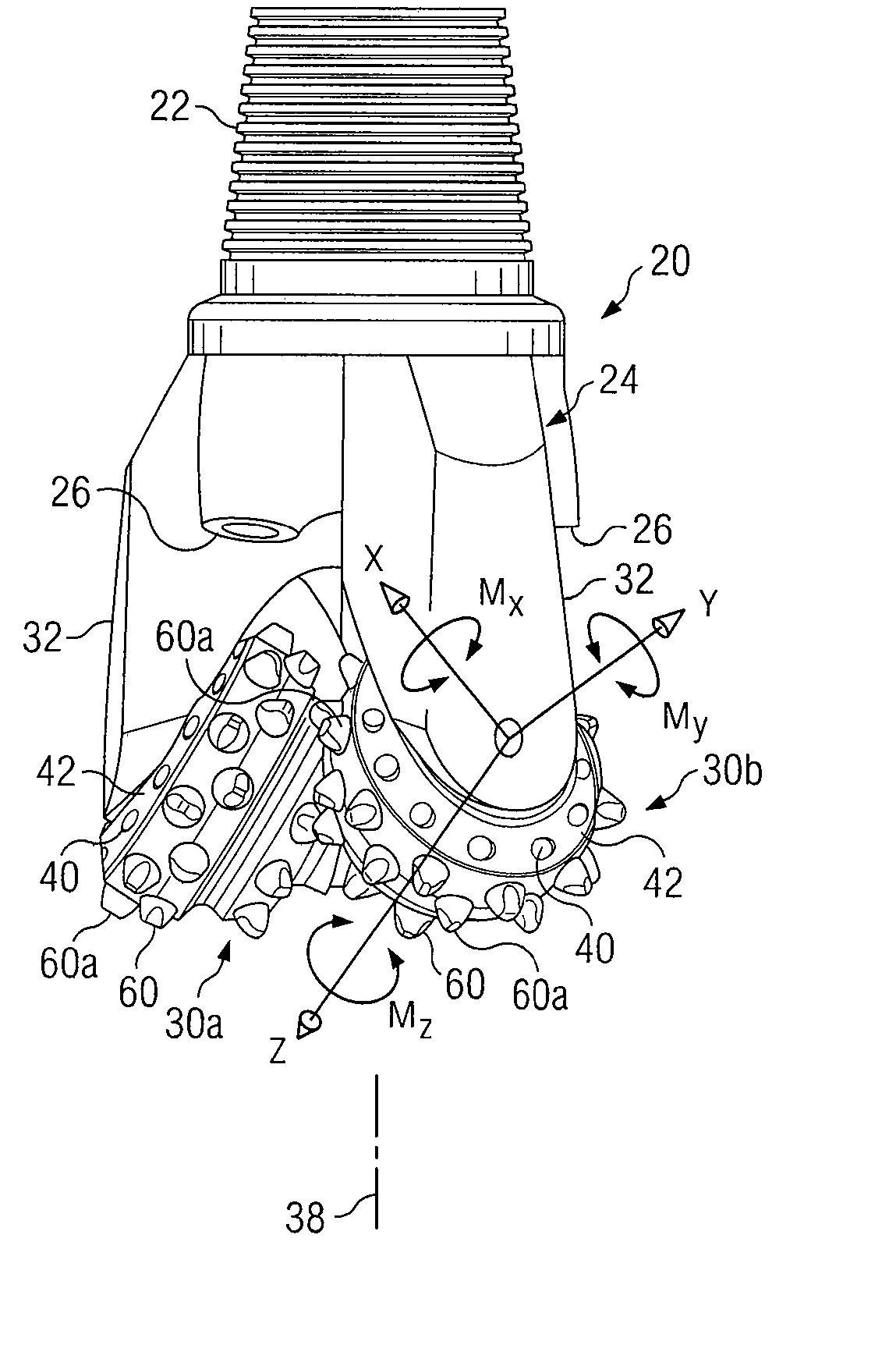
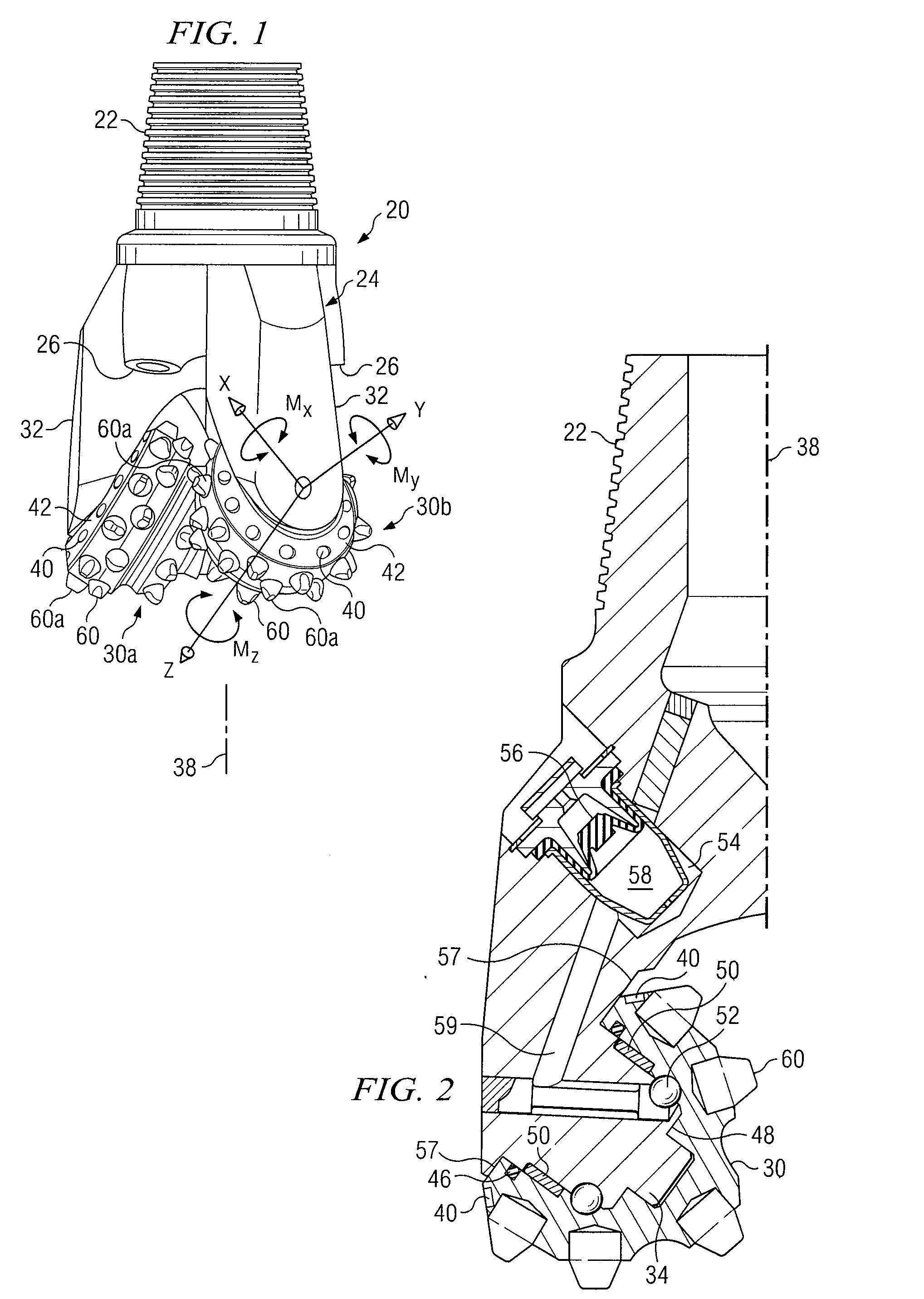
[0049] Preferred embodiments and their advantages are best understood by reference to FIGS. 1-22 wherein like numbers refer to like and corresponding parts.

[0050] The terms “cutting element” and “cutting elements” may be used in this application to include various types of compacts, inserts, milled teeth and welded compacts satisfactory for use with roller cone drill bits. The terms “cutting structure” and “cutting structures” may be used in this application to include various combinations and arrangements of cutting elements formed on or attached to one or more cone assemblies of a roller cone drill bit.

[0051] The term “cone assembly” may be used in this application to include various types and shapes of roller cone assemblies and cutter cone assemblies rotatably mounted to a drill bit support arm. Cone assemblies may have a conical exterior shape or may have a more rounded exterior shape. In certain embodiments, cone assemblies may incorporate an exterior shape having or approac...


PUM


Abstract

A roller cone drill bit may include optimally designed bearing structures and cutting structures. The roller cone drill bit may include three cone assemblies rotatably mounted on respective spindles via respective bearing structures. Each cone assembly may have a respective cutting structure with a minimal moment center located along each respective axis of rotation. Each respective bearing structure has a center point located proximate each respective minimal moment center.

Description

RELATED APPLICATIONS [0001] This application is a divisional of U.S. patent application Ser. No. 11 / 202,878, filed Aug. 12, 2005, entitled Roller Cone Drill Bits with Optimized Bearing Structures, which claims the benefit of U.S. Provisional Patent Application Ser. No. 60 / 601,952, filed Aug. 16, 2004, entitled Roller Cone Drill Bits with Optimized Bearing Structures. [0002] This application is related to copending U.S. application Ser. No. 10 / 919,990 filed Aug. 17, 2004 which claims the benefit of U.S. Provisional Patent Application Ser. No. 60 / 549,339 filed Mar. 2, 2004 entitled, Roller Cone Drill Bits with Enhanced Drilling Stability and Extended Life of Associated Bearings and Seals and U.S. Continuation-In-Part application Ser. No. 11 / 054,395 filed Feb. 9, 2005 which claims the benefit of U.S. Provisional Patent Application Ser. No. 60 / 549,354 filed Mar. 2, 2004 entitled, Roller Cone Drill Bits with Enhanced Cutting Elements and Cutting Structures.TECHNICAL FIELD [0003] The pres...

Claims


Application Information

Patent Timeline
Patent Type & Authority Applications(United States)
IPC IPC(8): E21B10/08E21B10/16E21B10/22E21B41/00
CPCE21B10/22E21B10/16
Inventor CHEN, SHILINSUI, PING C.
Owner HALLIBURTON ENERGY SERVICES INC
Why Eureka
Try Eureka